3D printing sprayer

A 3D printing and 3D printer technology, applied in the field of 3D printing, can solve the problems of limited spraying speed, inability to depict details, and inability to guarantee the accuracy of the printing process, and achieve good molding speed, molding effect, and high precision.

Active Publication Date: 2018-12-18
如东道博智能设备有限公司
View PDF9 Cites 4 Cited by
  • Summary
  • Abstract
  • Description
  • Claims
  • Application Information

AI Technical Summary

Problems solved by technology

The difference between them is that they use available materials and build parts in different layers. In the 3D printing process, light-cured materials can be used for rapid prototyping of medical, toy and other fields. The prototyping process saves materials, but in When printing with existing 3D printers, due to the fixed size of the nozzle of the spraying material, the spraying speed is limited in the process of fast spraying and forming, and the details cannot be detailed when drawing details, so that the accuracy of the printing process cannot be guaranteed.

Method used


Image

  • 3D printing sprayer
  • 3D printing sprayer
  • 3D printing sprayer

Examples


Embodiment approach

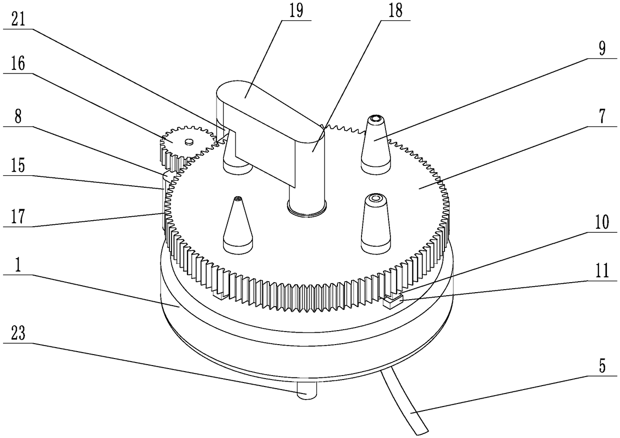
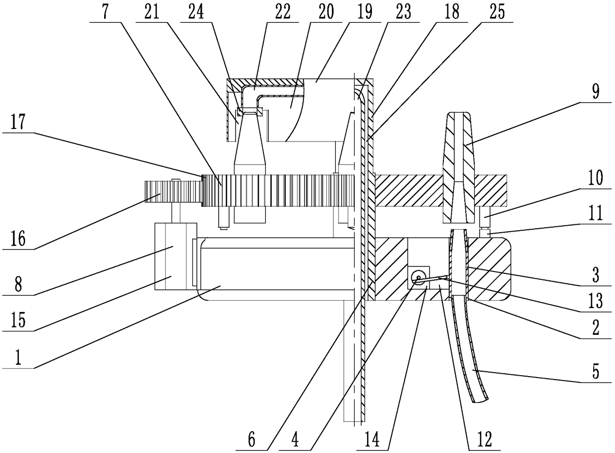
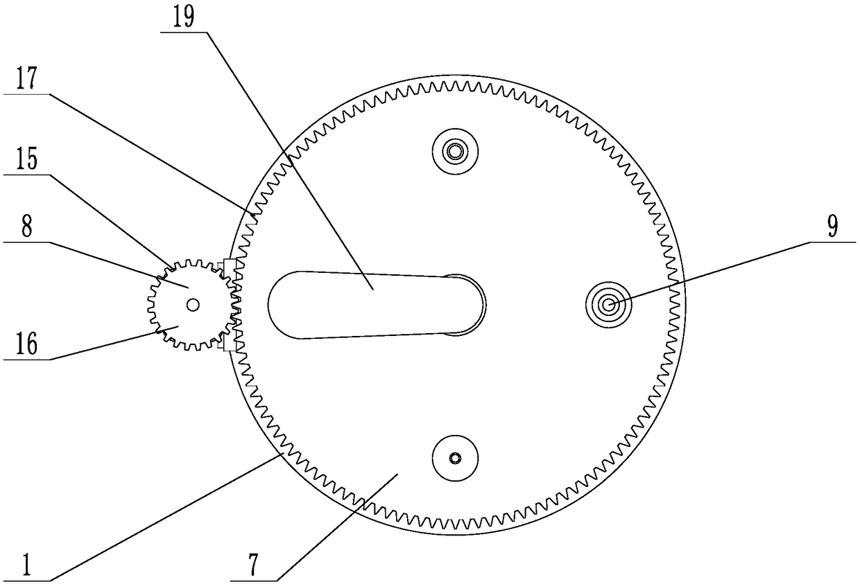
[0069] When the present invention is in use, the 3D printer controller imports the set program in advance, and the 3D printer controller controls the action of the second driving device 8, so that the rotating disk 7 rotates along the fixed axis 6, and the nozzles 9 on the rotating disk 7 follow the rotation of the rotating disk. 7 rotation, when the pre-set nozzle 9 rotates to the position matched with the retractable nozzle 3, the sensor 10 corresponding to the nozzle 9 is in contact with the trigger 11, and the sensor transmits the signal to the 3D printer controller, the 3D printer The controller controls the second driving device 8 to stop, so that the nozzle 9 stops at the coaxial position with the telescopic nozzle 3, and then the 3D printer controller controls the first driving device 4 to move, and the first driving device 4 drives the telescopic nozzle 3 to a fixed position. The mounting hole 2 on the disk 1 slides inside, so that the head of the telescopic nozzle 3 i...

Embodiment

[0071] A 3D printing nozzle, comprising a fixed plate 1, an installation hole 2 is provided on the fixed plate 1; a telescopic nozzle 3 is arranged in the installation hole, and the telescopic nozzle 3 can slide in the installation hole 2; The first driving device 4 connected with the signal of the 3D printer controller is set, the first driving device 4 is compatible with the telescopic nozzle 3, and the first driving device 4 is used to drive the telescopic nozzle 3 to slide in the installation hole 2, this In the embodiment, the first driving device 4 includes a mounting groove 12, the mounting groove 12 is located on one side of the mounting hole 2, a connecting rod 13 and a first motor 14 are arranged in the mounting groove, and one end of the connecting rod 13 is connected to the telescopic The nozzle 3 is hinged, the first motor 14 is fixed to the side wall of the installation groove 12 by bolts, the first motor 14 is connected to the 3D printer controller signal, and th...


PUM


Abstract

The invention provides a 3D printing sprayer, and mainly relates to the field of 3D printing. The 3D printing sprayer includes a fixing disk, a telescopic mouth, a first driving device, a connecting pipe, a fixed shaft, a rotating disk, a second driving device, a plurality of nozzles, sensors and a trigger block, wherein the fixing disk is provided with an installation hole, the telescopic mouth is connected with the installation hole in a sliding mode, the first drive device is connected with a 3D printer controller, the connecting pipe is a hose, the fixed shaft is vertically and fixedly connected with the central position of the fixing disk, the rotating disk is connected with the fixed shaft in a rotating mode, the second driving device is connected with the 3D printer controller, thenozzles are detachably and vertically fixedly connected to the top face of the rotating disk, the sensors correspond to the nozzles one by one, and the trigger block is located on the end, facing therotating disk, of the fixing disk. The 3D printing sprayer has the beneficial effects that the molding speed and the molding effect of appliances can be preferably controlled, and the accuracy in theprinting process is higher.

Description

technical field [0001] The invention mainly relates to the field of 3D printing, in particular to a 3D printing nozzle. Background technique [0002] 3D printing (3DP) is a kind of rapid prototyping technology. It is a technology based on digital model files, using rapid prototyping materials, and constructing objects by layer-by-layer printing. There are many different technologies for 3D printing. The difference between them is that they use available materials and build parts in different layers. In the 3D printing process, light-cured materials can be used for rapid prototyping of medical, toy and other fields. The prototyping process saves materials, but in When printing with existing 3D printers, due to the fixed size of the nozzle of the spraying material, the spraying speed is limited in the process of fast spraying and forming, and the details cannot be detailed when drawing details, so that the accuracy of the printing process cannot be guaranteed. . Contents o...

Claims


Application Information

Patent Timeline
IPC IPC(8): B29C64/106B29C64/209B29C64/227B33Y30/00
CPCB29C64/106B29C64/209B29C64/227B33Y30/00
Inventor 刘兆云
Owner 如东道博智能设备有限公司
Why Eureka
Try Eureka