Al technical title is built by PatSnap Al team. It summarizes the technical point description of the patent document.
A waste paper baler, waste paper technology, applied in the direction of presses, manufacturing tools, etc., can solve the problems of easy generation of dust, incomplete compression, unfavorable workshop cleaning, etc., to reduce transportation costs, avoid dust escape, and ensure cleanliness Effect
Inactive Publication Date: 2018-12-18
江门市厚润纸制品有限公司
View PDF0 Cites 1 Cited by
Summary
Abstract
Description
Claims
Application Information
AI Technical Summary
This helps you quickly interpret patents by identifying the three key elements:
Problems solved by technology
Method used
Benefits of technology
Problems solved by technology
Dust is easily generated during the production process of the existing compressor, and the shortcomings of incomplete compression
Dust is not only not conducive to the cleaning of the workshop, but also threatens the health of nearby workers. Incomplete compression will increase the transportation cost of waste paper in disguise
Method used
Image
Click on the blue label to locate the original text in one second.
Reading with bidirectional positioning of images and text.
Examples
Embodiment Construction
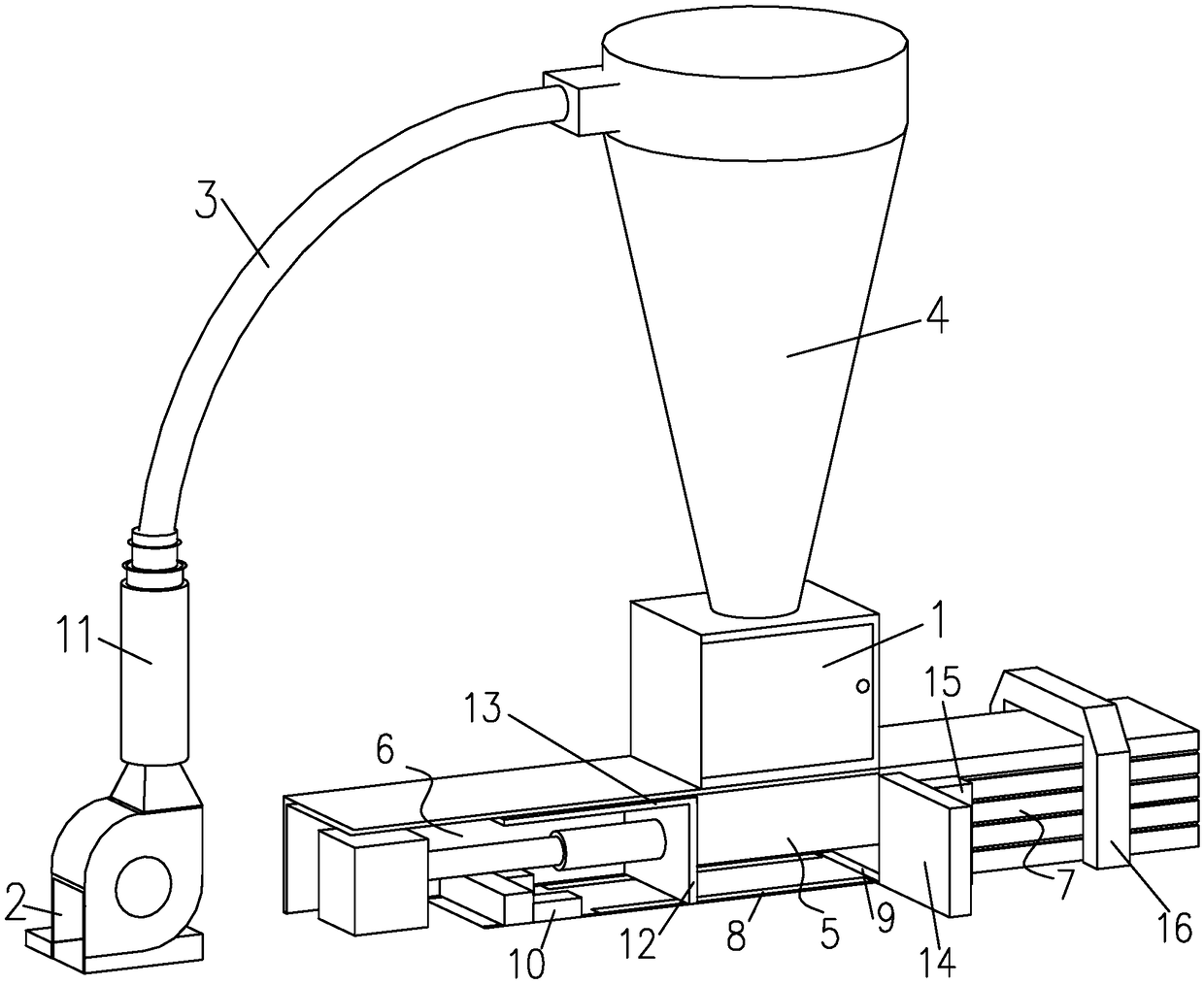
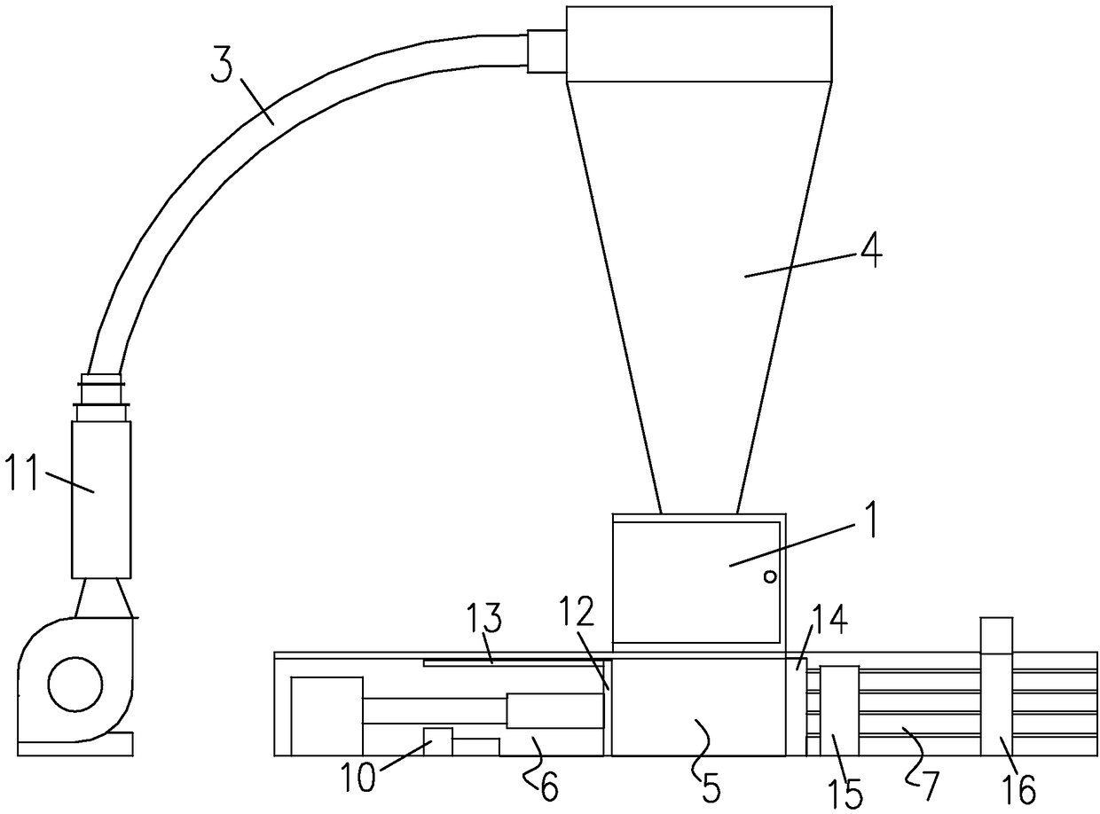
[0020] See attached Figure 1-2 , a waste paper baler according to an embodiment of the present invention, comprising a feed box 1, including a feed box, the inner wall of the feed box 1 is provided with a spray device for spraying water on the waste paper; the feed box 1 is connected with a closed feeding device, which includes a sequentially connected feeding port 2, a feeding pipeline 3, a funnel 4, and a fan for sucking waste paper into the feeding device, and the funnel 4 is vertical placed, the discharge end of the funnel 4 is connected to the feed box 1; a compression chamber 5 is provided below the feed box 1, and tool chambers connected to the compression chamber 5 are respectively provided on both sides of the compression chamber 5 6 and a paper outlet chamber 7; the tool chamber 6 is provided with a propulsion mechanism, the compression chamber 5 is provided with a first guide rail 8 that guides the advancement mechanism, and the connection between the compression c...
PUM
Abstract
The invention discloses a waste paper packaging machine. The machine comprises a feeding box, a spraying device is arranged on the inner wall of the feeding box, a closed feeding device is connected above the feeding box, the feeding device comprises a feeding opening, a feeding pipeline, a hopper and a draught fan used for sucking waste paper into the feeding device, wherein the feeding opening,the feeding pipeline, the hopper and the draught fan are connected in sequence, the hopper is vertically placed, the discharging end of the hopper is connected with the feeding box, a compression cavity is arranged below the feeding box, a tool cavity and a paper outlet cavity which are connected with the compression cavity are formed in the two sides of the compression cavity, a propelling mechanism is arranged in the tool cavity, a first guide rail used for guiding the propelling mechanism to advance is arranged in the compression cavity, a baffle mechanism capable of moving is arranged at the joint of the compression cavity and the paper outlet cavity, the propelling mechanism carries out propelling in the direction, facing the baffle mechanism, of the first guide rail so as to compresswaste paper in the compression cavity, and a dust collector used for cleaning the first guide rail is arranged in the tool cavity. According to the waste paper packaging machine, dust escaping duringwork can be avoided, meanwhile, the baffle mechanism is added, and compression is more thorough.
Description
technical field [0001] The invention relates to the field of waste material collection, in particular to a waste paper baler. Background technique [0002] In the process of producing cartons or cartons, a lot of corner waste will be produced. The corner waste of paper products often occupies a large volume. It is very necessary to compress waste paper. Compression can greatly reduce the space it occupies. In the production process of the existing compressor, it is easy to generate dust, and has the disadvantage of incomplete compression. Dust is not only detrimental to the cleanliness of the workshop, but also threatens the health of nearby workers. Incomplete compression will increase the transportation cost of waste paper in disguise. Contents of the invention [0003] In order to overcome the shortcomings of the existing waste paper compressors, the invention provides a waste paper baler with a simple and reliable structure. [0004] The technical solution adopted by...
Claims
Application Information
Patent Timeline
Application Date:The date an application was filed.
Publication Date:The date a patent or application was officially published.
First Publication Date:The earliest publication date of a patent with the same application number.
Issue Date:Publication date of the patent grant document.
PCT Entry Date:The Entry date of PCT National Phase.
Estimated Expiry Date:The statutory expiry date of a patent right according to the Patent Law, and it is the longest term of protection that the patent right can achieve without the termination of the patent right due to other reasons(Term extension factor has been taken into account ).
Invalid Date:Actual expiry date is based on effective date or publication date of legal transaction data of invalid patent.