Ceramic tile laying and firm beating device used for building engineering

A technology for construction engineering and ceramic tiles, which is applied in the field of ceramic tile laying and compaction devices for construction engineering, can solve the problems of uncompacted ceramic tiles, insufficient mortar, and numbness of the staff's legs, so as to avoid the numbness of the legs and the moving up and down. smooth effect

Active Publication Date: 2018-12-18
苏州凯绚新科技有限公司
View PDF6 Cites 14 Cited by
  • Summary
  • Abstract
  • Description
  • Claims
  • Application Information

AI Technical Summary

Problems solved by technology

[0002] When building buildings, in order to make the building more beautiful, people will lay tiles on the ground. After laying the tiles, in order to avoid the mortar being full and causing the tiles to not be tight, the tiles need to be tapped. At present, the staff usually take Squatting on the tiles with a rubber hammer and tapping the tiles gently, the tiles are hardened. After a long time, the staff's legs are prone to numbness; in order to relieve the leg numbness, the staff will stand up and rest from time to time, which will affect the work efficiency

Method used


Image

  • Ceramic tile laying and firm beating device used for building engineering

Examples


Embodiment 1

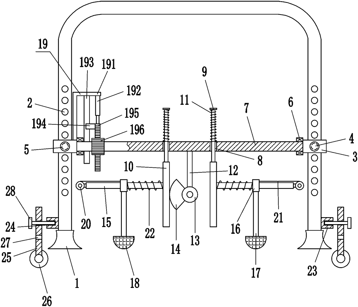
[0017] A kind of tile laying knocking device for building engineering, such as figure 1 As shown, it includes n-shaped frame 1, guide sleeve 3, first screw rod 5, bearing seat 6, cross bar 7, guide rod 9, first rack 10, first spring 11, vertical bar 12, motor 13, sector Gear 14, slide bar 15, sliding sleeve 16, connecting rod 17 and rubber block 18, the left and right sides of n-shaped frame 1 front side all have the first screw hole 2 at even intervals, and n-shaped frame 1 left and right sides are all provided with There is a guide sleeve 3, the front side of the guide sleeve 3 has a second screw hole 4, the second screw hole 4 and the first screw hole 2 are provided with a first screw 5, and the inner sides of the guide sleeve 3 on the left and right sides are installed with bearing seats 6 , there is a cross bar 7 connected between the two bearing seats 6, the left and right parts of the cross bar 7 are provided with guide holes 8, the two guide holes 8 are provided with g...

Embodiment 2

[0019] A kind of tile laying knocking device for building engineering, such as figure 1 As shown, it includes n-shaped frame 1, guide sleeve 3, first screw rod 5, bearing seat 6, cross bar 7, guide rod 9, first rack 10, first spring 11, vertical bar 12, motor 13, sector Gear 14, slide bar 15, sliding sleeve 16, connecting rod 17 and rubber block 18, the left and right sides of n-shaped frame 1 front side all have the first screw hole 2 at even intervals, and n-shaped frame 1 left and right sides are all provided with There is a guide sleeve 3, the front side of the guide sleeve 3 has a second screw hole 4, the second screw hole 4 and the first screw hole 2 are provided with a first screw 5, and the inner sides of the guide sleeve 3 on the left and right sides are installed with bearing seats 6 , there is a cross bar 7 connected between the two bearing seats 6, the left and right parts of the cross bar 7 are provided with guide holes 8, the two guide holes 8 are provided with g...

Embodiment 3

[0022] A kind of tile laying knocking device for building engineering, such as figure 1As shown, it includes n-shaped frame 1, guide sleeve 3, first screw rod 5, bearing seat 6, cross bar 7, guide rod 9, first rack 10, first spring 11, vertical bar 12, motor 13, sector Gear 14, slide bar 15, sliding sleeve 16, connecting rod 17 and rubber block 18, the left and right sides of n-shaped frame 1 front side all have the first screw hole 2 at even intervals, and n-shaped frame 1 left and right sides are all provided with There is a guide sleeve 3, the front side of the guide sleeve 3 has a second screw hole 4, the second screw hole 4 and the first screw hole 2 are provided with a first screw 5, and the inner sides of the guide sleeve 3 on the left and right sides are installed with bearing seats 6 , there is a cross bar 7 connected between the two bearing seats 6, the left and right parts of the cross bar 7 are provided with guide holes 8, the two guide holes 8 are provided with gu...


PUM


Abstract

The invention relates to a firm beating device, in particular to a ceramic tile laying and firm beating device used for building engineering. The ceramic tile laying and firm beating device used for building engineering can avoid that the legs of a worker are numb. In the technical implementation scheme, the ceramic tile laying and firm beating device used for building engineering comprises an n-shaped frame, guiding sleeves, first screw rods, a transverse rod, guide rods, first gear racks, first springs, a vertical rod, a motor, a sector-shaped gear, sliding rods, sliding sleeves and others;first screw holes are uniformly formed in the left side and the right side of the front side of the n-shaped frame at intervals, the guiding sleeves are arranged on the left side and the right side ofthe n-shaped frame respectively, second screw holes are formed in the front sides of the guiding sleeves, and the first screw rods are arranged in the second screw holes and the first screw holes. Anticlockwise rotation of the motor can make rubber blocks on the left side and the right side move vertically and constantly to firmly beat ceramic tiles, it is unnecessary to squat on the ceramic tiles for a long term for workers, and accordingly the legs of the workers can be prevented from being numb.

Description

technical field [0001] The invention relates to a compacting device, in particular to a compacting device for tile laying in construction engineering. Background technique [0002] When building buildings, in order to make the building more beautiful, people will lay tiles on the ground. After laying the tiles, in order to avoid the mortar being full and causing the tiles to not be tight, the tiles need to be tapped. At present, the staff usually take Squatting on the tiles with a rubber hammer and tapping the tiles gently, the tiles are hardened. After a long time, the staff's legs are prone to numbness; in order to relieve the leg numbness, the staff will stand up and rest from time to time, which will affect work efficiency. Contents of the invention [0003] In order to overcome the shortcoming that the staff needs to squat on the tiles with a rubber hammer and gently tap the tiles to knock the tiles firmly, the staff's legs are prone to numbness. Therefore, the techni...

Claims


Application Information

Patent Timeline
Patent Type & Authority Applications(China)
IPC IPC(8): E04F21/22
CPCE04F21/22
Inventor 李芬
Owner 苏州凯绚新科技有限公司
Why Eureka
Try Eureka