Universal decompression device and decompression method for marine hydraulic system

A hydraulic system and decompression device technology, applied in the direction of fluid pressure actuators, servo motors, servo meter circuits, etc., can solve the problems of high construction costs and large deck area occupied by hydraulic systems, and achieve reliability and safety. Effect

Active Publication Date: 2019-11-05
ZHEJIANG OCEAN UNIV
View PDF1 Cites 0 Cited by
  • Summary
  • Abstract
  • Description
  • Claims
  • Application Information

AI Technical Summary

Problems solved by technology

[0003] The purpose of the present invention is to provide a general-purpose decompression for marine hydraulic systems with stepless decompression and easy operation, aiming at the disadvantages or deficiencies of the existing ship deck machinery, such as high construction cost of the hydraulic system, repeated construction of the system, and large deck area. Device and pressure reducing method thereof

Method used


Image

  • Universal decompression device and decompression method for marine hydraulic system
  • Universal decompression device and decompression method for marine hydraulic system
  • Universal decompression device and decompression method for marine hydraulic system

Examples


Embodiment 1

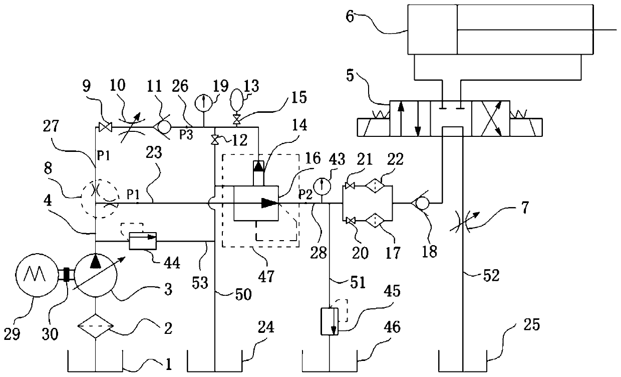
[0056] As shown in the figure, a general-purpose pressure reducing device for marine hydraulic systems includes an oil tank 1, a one-way variable hydraulic pump 3, an electric motor 29 and a fixed-value pressure reducing valve 47, the oil tank 1 and a one-way variable hydraulic pump 3 The first oil filter 2 is installed on the oil path of the oil circuit. The electric motor 29 drives the one-way variable hydraulic pump 3 to move through the coupling 30; the one-way variable hydraulic pump 3 is connected with an output pipeline 4, the output pipeline 4 The pressure reducing valve pilot line 27 and the pressure reducing valve inlet line 23 are respectively connected through the diverter valve 8;

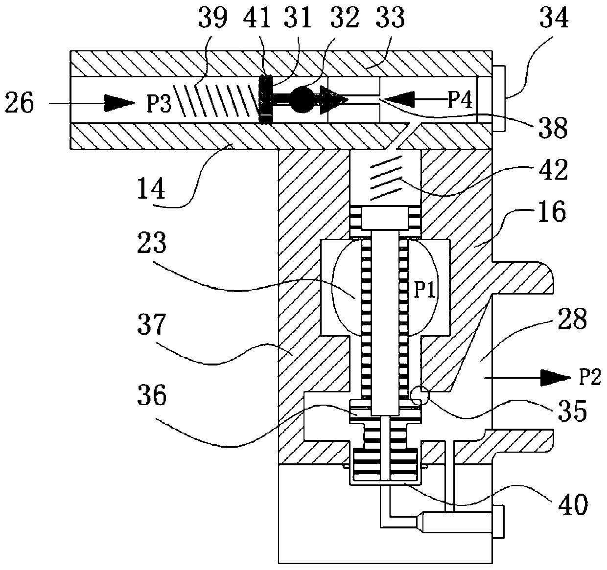
[0057] The fixed-value pressure reducing valve 47 includes the pilot valve 14 of the pilot pressure reducing valve and the main valve 16 of the pilot pressure reducing valve. The inlet pipe 23 of the pressure reducing valve is directly connected with the main valve 16 of the pilot pressure...


PUM


Abstract

The utility model relates to a general type decompression device of a marine hydraulic system. The general type decompression device comprises a first fuel tank, a one-way variable hydraulic pump, anelectric motor and a fixed-value decompression valve, first fuel filters are installed on the fuel paths of the first fuel tank and the one-way variable hydraulic pump, and the electric motor drives the one-way variable hydraulic pump to rotate through a coupling; and the general type decompression device is characterized in that an output pipeline is connected with the one-way variable hydraulicpump and connected with a decompression valve pilot pipeline and a decompression valve inlet pipeline. The general type decompression device has the beneficial effects that the general type decompression device of the marine hydraulic system only has one power source of the one-way variable hydraulic pump, according to the actual needs, by adjusting the flow area A of an adjustable overflow valvetwo section throttle opening, the pressure source of any size required by ship deck machinery or device can be obtained, and the needs of the normal working condition of the hydraulic machinery of different ship decks and the pressure source of any size under various conditions are met.

Description

Technical field [0001] The invention relates to a general pressure reducing device and a pressure reducing method for a marine hydraulic system, and belongs to the technical field of ship machinery. Background technique [0002] On the ship’s deck, there are many hydraulic machinery or devices, such as hatch cover opening and closing devices, windlasses, cable winches, cranes, etc. Because each hydraulic machinery requires a different pressure source, each hydraulic Each machine needs to be equipped with a separate hydraulic system. As a result, each hydraulic machine has its own hydraulic oil tank, hydraulic pump, hydraulic control components and hydraulic accessories, etc. There are increased investment costs of the hydraulic system, repeated construction of the system, and waste of deck space. And other issues. For example, the publication number CN101863421B discloses a hydraulic system with a hydraulic control operation triple pump, including a first oil pump, a second oil ...

Claims


Application Information

Patent Timeline
Patent Type & Authority Patents(China)
IPC IPC(8): F15B11/028
CPCF15B11/028F15B2211/20515F15B2211/20546F15B2211/50554F15B2211/515
Inventor 朱发新刘伟卢金树李玉乐王伟军董良雄王帅军陈甜
Owner ZHEJIANG OCEAN UNIV
Why Eureka
Try Eureka