Method for improving bridge deflection testing precision based on inclinometer

A technology for testing accuracy and deflection of bridges. It is used in elastic testing, machine/structural component testing, and instrumentation. It can solve problems such as confirmatory testing under stay, limiting the popularization and application of inclinometers, and failing to consider the impact of testing accuracy. , to achieve real-time monitoring, improve test accuracy, and improve calculation accuracy.

Active Publication Date: 2018-12-18
JIANGSU PROVINCIAL COMM PLANNING & DESIGN INST +1
View PDF5 Cites 20 Cited by
  • Summary
  • Abstract
  • Description
  • Claims
  • Application Information

AI Technical Summary

Problems solved by technology

In addition, the deflection monitoring technology based on the inclinometer mostly stays in the verification test or static test process. For example, the patent No. 201610260622.7 only provides a bridge deflection calculation method, which do...

Method used


Image

  • Method for improving bridge deflection testing precision based on inclinometer
  • Method for improving bridge deflection testing precision based on inclinometer
  • Method for improving bridge deflection testing precision based on inclinometer

Examples


example 1

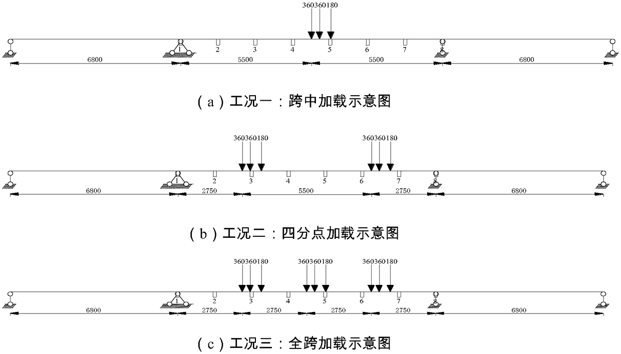
[0058] Taking a (68+110+68)m three-span continuous girder bridge as the engineering background, the deflection calculation and analysis of its main span is carried out by selecting representative loading conditions. The inclination response of each measuring point in the longitudinal direction of the bridge deck under various working conditions is simulated by finite element analysis software, and then the calculated deflection value in the direction of the longitudinal axis of the bridge is obtained by using four algorithms. The multiple designated positions this time are the 7 equal points of the midspan, that is, there are 8 designated positions in total.

[0059] Table 1 Deflection conversion results of different algorithms (unit: mm)

[0060]

[0061] The schematic diagram of typical loading conditions is as follows: figure 1 As shown, the results of the four algorithms under each loading scheme are shown in Table 1. In general, the spline function fitting method base...

example 2

[0063] 1. Project overview

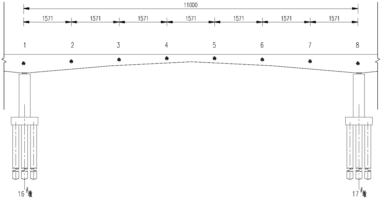
[0064] Taking a (68+110+68)m three-span continuous girder bridge as the engineering background, a representative loading condition was selected to monitor the deflection of its main span, and multiple designated positions were the 7 equal points of the mid-span, that is, a total of 8 specified location, such as image 3 shown.

[0065] 2. Temperature drift error correction

[0066] Such as Figure 4 As shown, the temperature of 20 inclinometers was calibrated using a three-axis high-precision turntable, and the temperature error compensation formula of each inclinometer was obtained, so that the temperature drift error correction of the inclination values ​​obtained by each inclinometer can be performed later.

[0067] 3. Noise signal elimination

[0068] A barrier-free driving test was carried out on the target bridge with a total weight of 50 tons of front four and rear eight vehicles. The vehicle speeds were 10km / h, 40km / h and 80km / h respect...


PUM


Abstract

The invention discloses a method for improving bridge deflection testing precision based on an inclinometer. The method is mainly used for improving the bridge deflection testing precision by three aspects of temperature error compensation, improvement of signal-to-noise ratio through band-pass filtering, and improvement of a deflection calculation method based on a dip angle value. The method comprises the following steps of a, carrying out temperature calibration on a to-be-used inclinometer in a one-to-one manner, b, acquiring inclination angles corresponding to a plurality of designated positions on the bridge, c, carrying out temperature drift error correction on the obtained inclination angle values by adopting respective pre-calibrated inclinometer temperature error compensation formulas, d, adopting a band-pass filtering algorithm for preprocessing the dip angle values, and eliminating noise influence, and e, adopting an improved conformal spline function fitting method to calculate the bridge deflection. According to the method, on one hand, the inclinometer measuring point arrangement is free of any restriction, and on the other hand, the calculation precision of an original test method is greatly improved, and the dynamic deflection of the bridge can be monitored in real time.

Description

technical field [0001] The invention relates to a method for improving the test accuracy of bridge deflection based on an inclinometer, belonging to the field of bridge structure deflection monitoring. Background technique [0002] The deflection deformation of the bridge is an intuitive response to the overall deformation and load bearing capacity of the bridge. Therefore, the changes in the overall deformation and load bearing capacity of the bridge can be evaluated by observing the changes in the vertical deflection of the bridge for a long time. At present, the relatively mature detection methods at home and abroad mainly include: electronic dial indicator, GPS, connected pipe liquid level type, and optical-based deflection measurement. For super-large projects such as cross-river bridges, deflection monitoring schemes based on GPS are mostly used; however, due to accuracy or reliability reasons, these methods are difficult to apply to bridges with a span of 50m to 200m...

Claims


Application Information

Patent Timeline
IPC IPC(8): G01M5/00
CPCG01M5/0008
Inventor 刘龑王文剑李波章世祥
Owner JIANGSU PROVINCIAL COMM PLANNING & DESIGN INST
Why Eureka
Try Eureka