Soil moisture monitor for direct-connected vacuum pressure gauge

A vacuum pressure gauge and soil moisture technology, applied in soil material testing, instruments, measuring devices, etc., can solve the problems of inconvenient operation, large volume of the negative pressure gauge, easy air intake of the vacuum pressure gauge, etc. Simple, small size effect

Active Publication Date: 2018-12-18
FARMLAND IRRIGATION RES INST CHINESE ACAD OF AGRI SCI
View PDF11 Cites 0 Cited by
  • Summary
  • Abstract
  • Description
  • Claims
  • Application Information

AI Technical Summary

Problems solved by technology

[0004] The invention provides a soil moisture monitor directly connected to a vacuum pressure gauge, which solves the problem of the large volume and inconvenient operation of the existing negative pressure gauge; Practical problems with easy air intake

Method used


Image

  • Soil moisture monitor for direct-connected vacuum pressure gauge
  • Soil moisture monitor for direct-connected vacuum pressure gauge
  • Soil moisture monitor for direct-connected vacuum pressure gauge

Examples


Embodiment 1

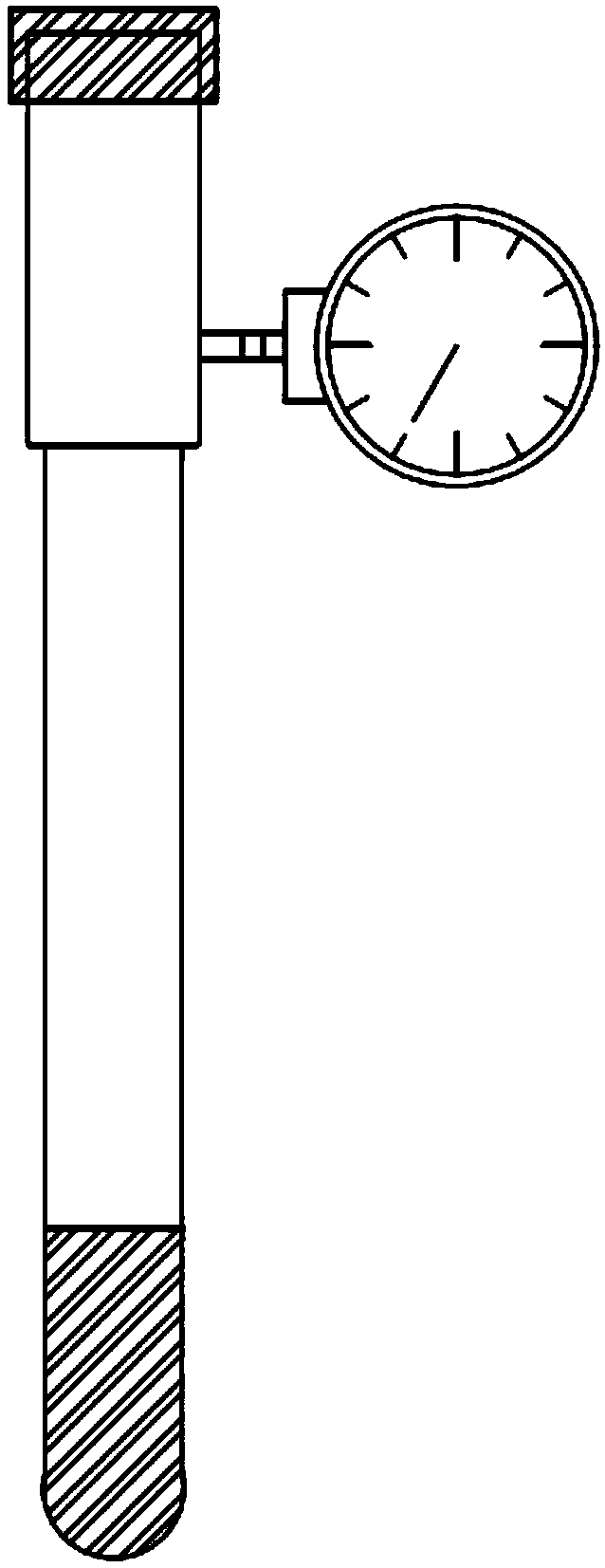
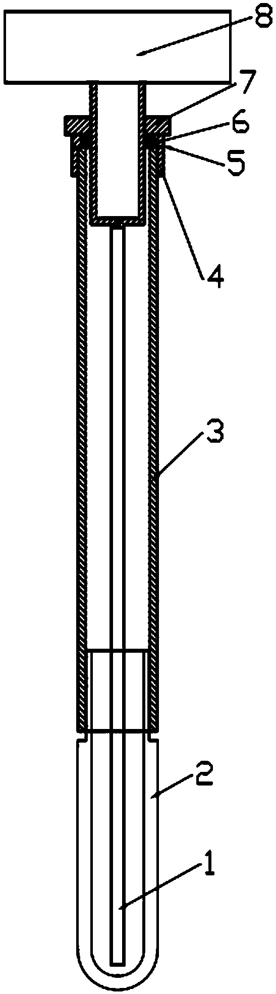
[0025] Such as figure 2 As shown, a soil moisture monitor directly connected to a vacuum pressure gauge includes a vacuum pressure gauge, a sealing device, a plastic hose 1, an air collection chamber 3 and a clay head 2. One end of the chamber 3 is connected, the other end of the gas collection chamber 3 is connected to the clay head 2, one end of the plastic hose 1 is connected to the air inlet of the vacuum pressure gauge, and the other end of the plastic hose 1 Deep into the clay head 2, 1-2cm away from the bottom of the clay head 2. The vacuum pressure gauge is an axial vacuum pressure gauge 8.

[0026] The gas collection chamber 3 is a transparent plastic tube or a plexiglass tube, and the present embodiment adopts a plexiglass tube.

[0027] The sealing device includes a rubber gasket 6 and an inner threaded joint. The inner threaded joint includes a threaded connection part 7, a rubber gasket installation part 5 and an air collection chamber connection part 4. The va...

Embodiment 2

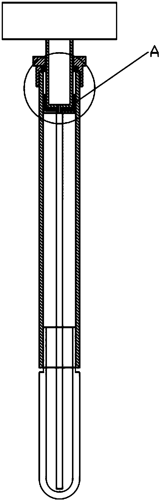
[0030] Such as image 3 and 4 As shown, a soil moisture monitor directly connected to a vacuum pressure gauge includes a vacuum pressure gauge, a sealing device, a plastic hose 1, an air collection chamber 3 and a clay head 2. One end of the chamber 3 is connected, the other end of the gas collection chamber 3 is connected to the clay head 2, one end of the plastic hose 1 is connected to the air inlet of the vacuum pressure gauge, and the other end of the plastic hose 1 Deep into the clay head 2, 1-2cm away from the bottom of the clay head 2. The vacuum pressure gauge is an axial vacuum pressure gauge 8.

[0031] The gas collection chamber 3 is a transparent plastic tube or a plexiglass tube, and the present embodiment adopts a plexiglass tube.

[0032] The sealing device includes a rubber gasket 6 and an inner threaded joint. The inner threaded joint includes a threaded connection part 7, a rubber gasket installation part 5 and an air collection chamber connection part 4. ...


PUM


Abstract

The invention relates to a soil moisture monitor for a direct-connected vacuum pressure gauge, which comprises a vacuum pressure gauge, a sealing device, a plastic hose, a gas collecting chamber and aclay cup. The vacuum pressure gauge is connected with one end of the gas collecting chamber through the sealing device, and the other end of the gas collecting chamber is connected with the clay cup;one end of the plastic hose is connected with an air inlet of the vacuum pressure gauge, and the other end of the plastic hose penetrates to the bottom of the gas collecting chamber. The vacuum pressure gauge of the invention is directly connected to an upper port of the gas collecting chamber and is overlooked for reading; a long plastic hose is mounted to the air inlet of the vacuum pressure gauge and can be inserted to the lower part of a negative pressure gauge water tube; the structure is simple and the volume is small; moreover, the vacuum pressure gauge and the gas collecting chamberare provided with an arm of force less than 5cm, the vacuum pressure gauge is not easy to get air inflow and water loss, and the failure rate is low. The soil moisture monitor for a direct-connected vacuum pressure gauge is suitable for ordinary people in agricultural production without strict training.

Description

technical field [0001] The invention relates to a soil moisture monitor directly connected to a vacuum pressure gauge, which belongs to the field of soil moisture measuring devices. Background technique [0002] my country is a large agricultural country, and maintaining the normal growth of crops requires a suitable soil moisture environment, but what crops are most sensitive to soil moisture is not the absolute content of soil moisture, but the soil water potential with its energy state. The negative pressure gauge is an instrument for measuring the ability of soil to supply crop moisture. Different textures of soil have different abilities to retain soil moisture. Although the water content is the same, the amount of water absorbed by the supplied crops is different. The negative pressure gauge can well detect the water supply capacity of soil with different textures. It has a simple structure and is easy to operate. [0003] There are many types of negative pressure gau...

Claims


Application Information

Patent Timeline
Patent Type & Authority Applications(China)
IPC IPC(8): G01N33/24
CPCG01N33/246
Inventor 冯俊杰贾艳辉孙浩杨慎骄刘平郭大应
Owner FARMLAND IRRIGATION RES INST CHINESE ACAD OF AGRI SCI
Why Eureka
Try Eureka