
Claw pole magnetic property nondestructive testing device and method adjustable in test temperature

A technology for testing temperature and non-destructive testing, applied in the direction of magnetic performance measurement, measuring device, measuring magnetic variables, etc., can solve the problem of non-destructive testing of magnetic performance of claw poles, etc., and achieve the effect of optimal design

Active Publication Date: 2018-12-18
JIANGSU LONGCHENG PREC FORGING CO LTD +1
View PDF7 Cites 6 Cited by
  • Summary
  • Abstract
  • Description
  • Claims
  • Application Information

AI Technical Summary

Problems solved by technology

[0003] Aiming at the defect that the existing technology cannot realize nondestructive testing of claw pole magnetic properties, the present invention proposes a nondestructive testing device and method for claw pole magnetic properties with adjustable test temperature. According to the magnetic circuit characteristics of claw pole generators, the generator is simulated Temperature conditions during operation, build a working magnetic field distribution that is highly similar to the actual generator and do not destroy the claw pole parts during the test

Method used


Image

  • Claw pole magnetic property nondestructive testing device and method adjustable in test temperature
  • Claw pole magnetic property nondestructive testing device and method adjustable in test temperature
  • Claw pole magnetic property nondestructive testing device and method adjustable in test temperature

Examples


Embodiment Construction

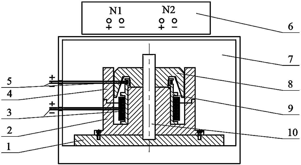
[0018] Such as figure 1 As shown, it is a non-destructive testing device for claw pole magnetic properties with adjustable test temperature involved in this example, wherein: the magnetic conducting ring 4 is connected to the hole shaft of the positioning base 2, and the winding ferrule 9 is connected to the center boss of the positioning base 2 The hole shafts are connected, the positioning shaft 10 passes through the center hole of the positioning base 2 and is connected to the magnetic isolation backing plate 1, and the positioning base 2 is connected to the magnetic isolation backing plate 1 through screws.

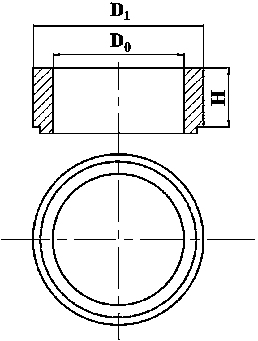
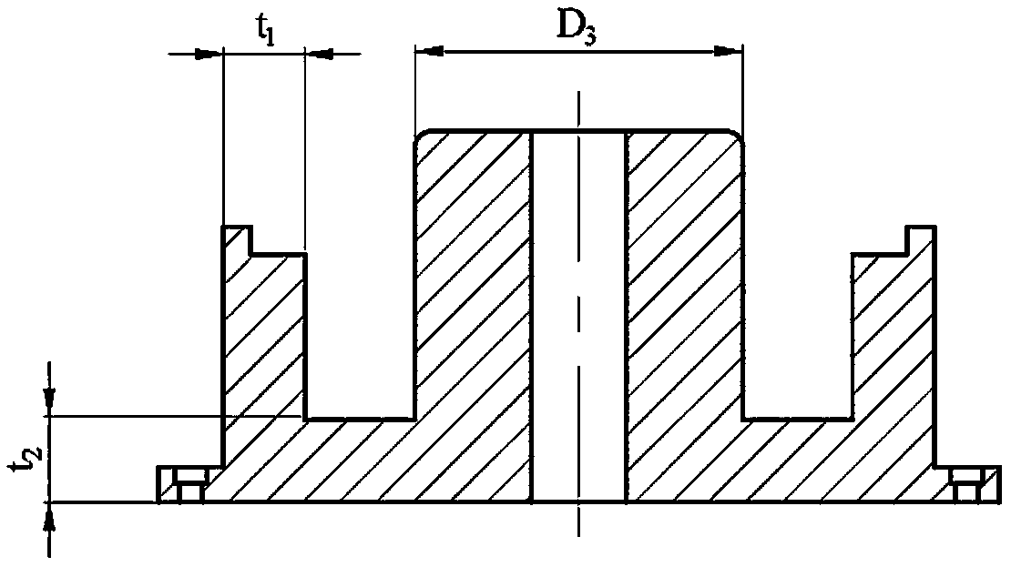
[0019] Such as figure 2 As shown, the total height of the magnetic permeable ring 4 is 1.1 to 1.2 times the total height of the claw pole parts to be tested; its inner diameter D 0 The difference from the outer diameter of the claw pole part to be tested is 0.4-0.8mm; the outer diameter Where: S 爪极 is the cross-sectional area of ​​the central boss of the claw pol...


PUM


Abstract

The invention relates to a claw pole magnetic property nondestructive testing device and method adjustable in test temperature. The device comprises a pedestal arranged in an incubator in a magnetismisolating way, a winding ferrule and an excitation coil which are arranged on the pedestal from inside to outside as well as a to-be-tested claw pole part arranged at the top of the pedestal, whereina measuring coil is arranged in the to-be-tested claw pole part, a magnetic conductive ring forming a magnetic field loop with the to-be-tested claw pole part is arranged outside the measuring coil, the excitation coil is connected with a direct current magnetic property measuring instrument and receives an excitation voltage, the measuring coil outputs an induced current to the direct current magnetic property measuring instrument by generating the induced current, the direct current magnetic property measuring instrument records an output excitation current, the detected induced current is converted into an induced voltage and integration is performed on the induced voltage in the time domain to obtain magnetic induction intensity, the whole magnetizing curve of the to-be-tested claw pole part is obtained through measuring and calculating, and magnetic permeability of the claw pole part is represented. The device provided by the invention constructs operating magnetic field distribution highly similar to the actual generator by simulating temperature conditions in a generator operation process according to magnetic circuit characteristics of a claw pole type generator, thus rapidtesting is performed.

Description

technical field [0001] The present invention relates to a technology in the field of generator magnetic performance detection, in particular to a non-destructive detection device and method for claw pole magnetic performance with adjustable test temperature. Background technique [0002] Claw pole alternators are the most common type of alternator used in automobiles. A pair of claw poles cooperate with each other to form the magnetic poles of the rotor, which are magnetized and form a magnetic field under the action of the excitation coil, and the rotating cutting stator coil induces a voltage to realize power generation. Improving the magnetic properties of the claw pole parts can directly improve the power generation efficiency of the claw pole generator at the same speed. In practice, there are many different claw pole manufacturing processes and raw materials. How to measure and evaluate the overall magnetic properties of claw poles and guide the optimization of its ma...

Claims


Application Information

Patent Timeline
IPC IPC(8): G01R33/12G01R33/04G01R33/10G01R33/06
CPCG01R33/04G01R33/06G01R33/10G01R33/1215G01R33/1223G01R33/1253
Inventor 汤晓峰胡成亮汤敏俊孙伟郑俊涛赵震
Owner JIANGSU LONGCHENG PREC FORGING CO LTD
Learn More