Design method for HIL test system, and HIL test system

A test system and design method technology, applied in the general control system, control/regulation system, instrument, etc., can solve the problem of the inability to realize the joint HIL test of multiple controllers, the inability to realize the HIL test of the engine controller, and the failure to build a simulated engine and Issues such as plant model of related components

Inactive Publication Date: 2018-12-18
CHONGQING CHANGAN AUTOMOBILE CO LTD
View PDF5 Cites 21 Cited by
  • Summary
  • Abstract
  • Description
  • Claims
  • Application Information

AI Technical Summary

Problems solved by technology

The first type of HIL test system is suitable for HIL testing of single controllers (such as vehicle controllers, battery management systems and motor controllers, etc.). The controlled object model can only simulate the working characteristics of the controlled object corresponding to a single controller, but cannot simulate the working characteristics of the controlled object corresponding to other controllers, and thus cannot realize the joint HIL test of multiple controllers, that is, Unable to apply to the HIL test of the hybrid new energy vehicle power system that requires multiple controllers to work together
The second type of HIL test system is suitable for the joint HIL test of the three electric vehicles (battery, motor, and electronic control) of pure electric vehicles. Although the joint HIL test of multiple controllers can be realized, since pure electric vehicles do not include engines, The second type of HIL test system also does not build a controlled object model for simulating the engine and related components, so it cannot realize the HIL test of the engine controller, and it is also not suitable for pure electric, pure motor, and engine and motor hybrid drives. Hybrid new energy vehicle power system HIL test with multiple working modes

Method used


Image

  • Design method for HIL test system, and HIL test system
  • Design method for HIL test system, and HIL test system
  • Design method for HIL test system, and HIL test system

Examples


Embodiment Construction

[0029] The following will clearly and completely describe the technical solutions in the embodiments of the present invention in conjunction with the accompanying drawings in the embodiments of the present invention. Obviously, the described embodiments are only some of the embodiments of the present invention, not all of them. Based on the embodiments of the present invention, all other embodiments obtained by persons of ordinary skill in the art without making creative efforts belong to the protection scope of the present invention.

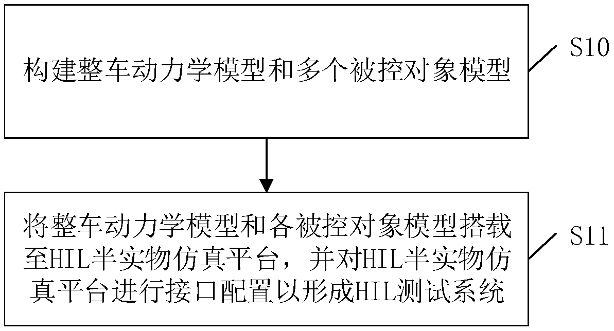
[0030] The object of the present invention is to provide a design method of an HIL test system and an HIL test system, which can make the HIL test system suitable for the HIL test of the hybrid power new energy vehicle power system.

[0031] In order to enable those skilled in the art to better understand the technical solution of the present invention, the present invention will be further described in detail below in conjunction with the accom...


PUM


Abstract

The invention discloses a design method for an HIL test system. The design method comprises the steps of building a complete vehicle dynamics model and a plurality of controlled object models at leastincluding an engine model, a power coupling mechanism model, a motor model and a battery model; carrying the complete vehicle dynamics model and the controlled object models on an HIL semi-physical simulation platform; performing interface configuration on the HIL semi-physical simulation platform, so that the finally formed HIL test system can be matched with cooperative work of an engine controller, a coupling mechanism controller, a motor controller and a battery management system in a power system of a hybrid power new energy automobile; and switching a pure-electric, pure-maneuver or engine and motor hybrid drive working mode of a virtual vehicle, so that the HIL test of the power system of the hybrid power new energy automobile is completed. In addition, the invention discloses theHIL test system, which has the abovementioned effects.

Description

technical field [0001] The invention relates to the field of new energy vehicles, in particular to a design method of an HIL test system and the HIL test system. Background technique [0002] With the increasing pressure of oil resource constraints and the increasing urgency of environmental protection, the development of new energy vehicles has become a social consensus, and hybrid new energy vehicles have also emerged as the times require. Moreover, since the power system plays a decisive role in the performance of hybrid new energy vehicles, it is of great significance to realize the HIL (hardware-in-the-loop) test of the power system of hybrid new energy vehicles. [0003] HIL test is an important verification method of system integration test in the development of new energy vehicle control strategy V process, which is realized based on HIL test system. In the prior art, HIL test systems can be roughly divided into two types. The first type of HIL test system is suita...

Claims


Application Information

Patent Timeline
Patent Type & Authority Applications(China)
IPC IPC(8): G05B17/02
CPCG05B17/02
Inventor 李晓弘翟钧时鹏王西乡缪涛方蔚
Owner CHONGQING CHANGAN AUTOMOBILE CO LTD
Why Eureka
Try Eureka