Friction mechanics demonstration device

A demonstration device, a technology of friction mechanics, applied in the field of teaching equipment, can solve the problems of experimental data error, difficult to achieve, large workload, etc., and achieve the effect of improving the accuracy of change, the range of change, and the convenience of viewing.

Pending Publication Date: 2018-12-18
ANHUI UNIV OF SCI & TECH
View PDF0 Cites 3 Cited by
  • Summary
  • Abstract
  • Description
  • Claims
  • Application Information

AI Technical Summary

Problems solved by technology

[0002] The friction mechanics experiment is an important part of the junior high school experiment. The key part of the experiment is to explore which factors are related to the size of the sliding friction force. However, the existing friction mechanics demonstration device has the following defects: 1. When doing the friction mechanics experiment, through People pull the spring dynamometer to make the object move in a straight line at a uniform speed, which is difficult to achieve in actual operation, resulting in errors in the experimental data; 2. The friction mechanics experiment is carried out on a horizontal plane, and generally only the pressure and pressure on the surface of the object can be tested. The impact of the roughness of the contact surface on the magnitude of the sliding friction, but this cannot test the relationship between the coefficient of dynamic friction and the inclination angle of the slope; 3. When doing the experiment, the experimental data needs to be artificially calculated and processed in the later stage to obtain the experimental results. The volume is relatively large, the demonstration effect is not good, and it is not real-time

Method used


Image

  • Friction mechanics demonstration device
  • Friction mechanics demonstration device
  • Friction mechanics demonstration device

Examples


Embodiment Construction

[0021] The following will clearly and completely describe the technical solutions in the embodiments of the present invention with reference to the accompanying drawings in the embodiments of the present invention. Obviously, the described embodiments are only some, not all, embodiments of the present invention. Based on the embodiments of the present invention, all other embodiments obtained by persons of ordinary skill in the art without making creative efforts belong to the protection scope of the present invention.

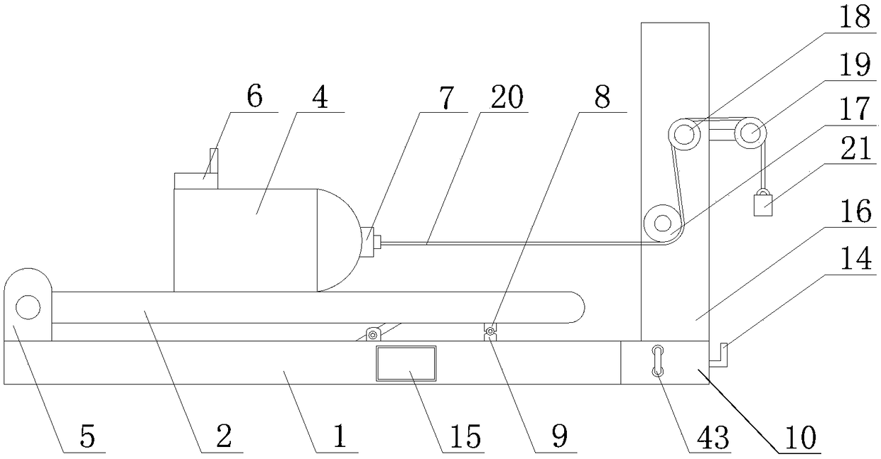
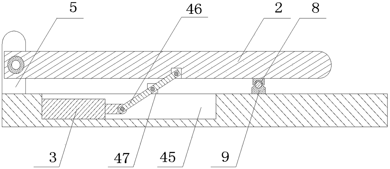
[0022] see Figure 1-6 , a friction mechanics demonstration device provided by the present invention includes a support plate 1, a friction plate 2, an electric push rod 3 and a friction body 4, the top of the support plate 1 is welded with a hinge block 5, and the hinge block 5 and the friction plate 2 Hinged, the support plate 1 has a groove 45, and the electric push rod 3 is installed inside the groove 45, the output end of the electric push rod 3 is hinged...


PUM


Abstract

The invention discloses a friction mechanics demonstration device comprising a support plate, a friction plate, an electric push rod and a friction body; the features are that the support plate top iswelded with a hinge block; the hinge block is hinged to the friction plate; the support plate has a groove; the electric push rod is arranged in the groove; the output end of the electric push rod ishinged to a connecting rod; the other end of the connecting rod is hinged to the bottom of the friction plate; a fixed block is arranged in the groove, and hinged to the middle of the connecting rod;the friction body top is provided with a wireless accelerometer; the friction body right end is provided with a wireless tension sensor. The demonstration device respectively uses the wireless accelerometer and the wireless tension sensor to measure the acceleration and the pulling force, thus reducing the test error; the friction plate tilt angle can be changed so as to realize multivariable influences on the friction force; the demonstration device uses a single chip to control the device and process the data, is strong in timeliness, small in error, and good in a demonstration effect.

Description

technical field [0001] The invention relates to the field of teaching equipment, in particular to a friction mechanics demonstration device. Background technique [0002] The friction mechanics experiment is an important part of the junior high school experiment. The key part of the experiment is to explore which factors are related to the size of the sliding friction force. However, the existing friction mechanics demonstration device has the following defects: 1. When doing the friction mechanics experiment, through People pull the spring dynamometer to make the object move in a straight line at a uniform speed, which is difficult to achieve in actual operation, resulting in errors in the experimental data; 2. The friction mechanics experiment is carried out on a horizontal plane, and generally only the pressure and pressure on the surface of the object can be tested. The impact of the roughness of the contact surface on the magnitude of the sliding friction, but this cann...

Claims


Application Information

Patent Timeline
IPC IPC(8): G09B23/10
CPCG09B23/10
Inventor 徐彬汪利萍姜志陈明亮
Owner ANHUI UNIV OF SCI & TECH
Why Eureka
Try Eureka