Optical compensation apparatus applied to panel and operating method thereof

An optical compensation and display panel technology, applied in static indicators, instruments, etc., to improve visual experience, correct uneven color defects, and avoid abnormal bright spots

Inactive Publication Date: 2018-12-18
RAYDIUM SEMICON
View PDF5 Cites 7 Cited by
  • Summary
  • Abstract
  • Description
  • Claims
  • Application Information

AI Technical Summary

Problems solved by technology

[0005] Therefore, the present invention proposes an optical compensation device applied to a display panel and its operation method to solve the problems encountered in the prior art

Method used


Image

  • Optical compensation apparatus applied to panel and operating method thereof
  • Optical compensation apparatus applied to panel and operating method thereof
  • Optical compensation apparatus applied to panel and operating method thereof

Examples


Embodiment Construction

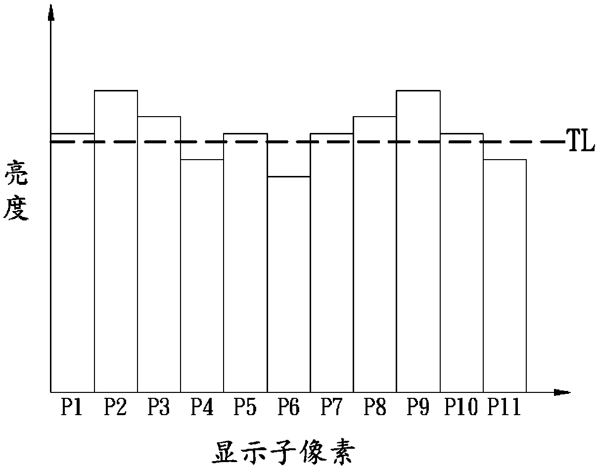
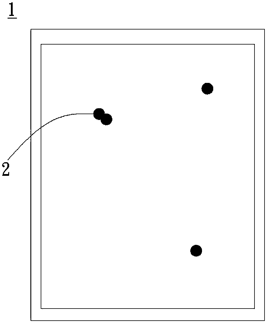
[0067] The invention discloses an optical compensation device and its operation method. In the process of measuring the brightness of all display sub-pixels of a display panel, even if there is dust or other disturbances on the display panel, the optical compensation device and its operation method of the present invention The method will first automatically detect these abnormal display sub-pixels and deal with them appropriately, so as to achieve the effect of color unevenness defect correction (Demura), and can effectively prevent the partial display of the display panel due to wrong optical compensation Unusual bright spots appear in sub-pixels.

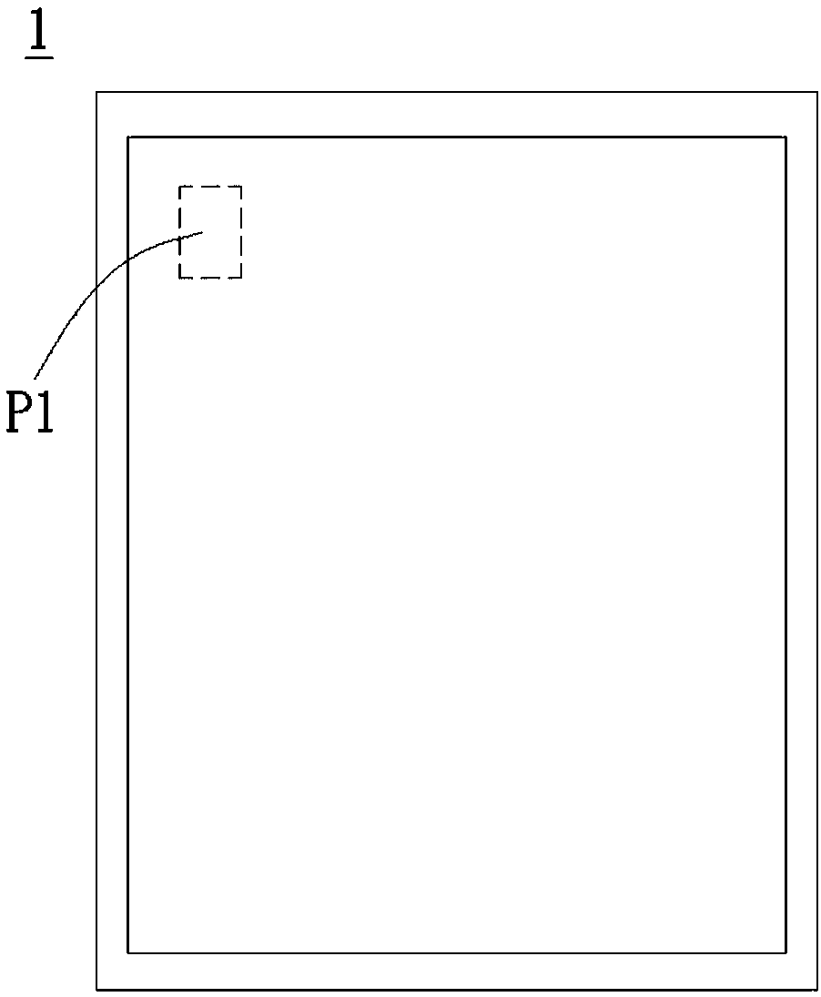
[0068] A preferred embodiment of the present invention is an optical compensation device. In this embodiment, the optical compensation device is applied to a display panel, such as an organic light emitting diode (OLED) display panel, but not limited thereto. The display panel includes a plurality of display sub-pixels for displ...


PUM


Abstract

An optical compensation apparatus applied to a panel and an operating method thereof are disclosed. The panel includes sub-pixels for displaying a display data. The optical compensation apparatus includes an optical measurement module, a data processing module and an optical compensation module. The optical measurement module is used to measure optical measurement values corresponding to the sub-pixels of the panel. The data processing module is coupled to the optical measurement module and used for determining whether the sub-pixels are abnormal according to the optical measurement values. Ifthe above determining result is yes, the data processing module generates at least one optical compensation value corresponding to at least one abnormal sub-pixel according to a specific processing rule. The optical compensation module is coupled to the data processing module and used for outputting the optical compensation value to perform optical compensation on the display data.

Description

technical field [0001] The present invention is related to the display panel, in particular to an optical compensation device applied to the display panel and its operation method. Background technique [0002] The current organic light-emitting diode (Organic Light-Emitting Diode, OLED) display panel often affects its yield rate due to color unevenness (mura). The so-called color unevenness (Mura) refers to various traces caused by uneven brightness of the display panel. Since color unevenness usually exists on the background of uneven light source, the human eye cannot effectively distinguish between normal images and color unevenness. flaw. Therefore, many technologies for correcting color unevenness (Demura) have emerged as the times require. [0003] The current common correction method for color unevenness is to first measure the brightness of each display sub-pixel of the display panel, so as to judge whether each display sub-pixel has color unevenness, and then cha...

Claims


Application Information

Patent Timeline
Patent Type & Authority Applications(China)
IPC IPC(8): G09G3/3208
CPCG09G3/3208G09G2330/10G09G3/006G09G3/2003G09G2310/027G09G2320/0233G09G2320/0242G09G2360/147
Inventor 唐尚平李弘
Owner RAYDIUM SEMICON
Why Eureka
Try Eureka