A push-pull mobile power cabinet device

A push-pull mobile power cabinet technology, which is applied in the direction of anti-seismic equipment, electrical components, substation/power distribution device shells, etc., can solve the problems of inconvenient inspection and maintenance, inconvenient external observation of power cabinets, and difficulty in cooling, so as to achieve easy maintenance and Maintenance, easy external observation, and improved heat dissipation effect

Inactive Publication Date: 2018-12-18
沈晨
View PDF5 Cites 10 Cited by
  • Summary
  • Abstract
  • Description
  • Claims
  • Application Information

AI Technical Summary

Problems solved by technology

[0002] The power cabinet usually consists of a cabinet body and a cabinet door. However, the inside of the conventional power cabinet usually lacks a support frame for the installation of electrical equipment, resulting in insufficient use of the internal space of the power cabinet, and the installation of electrical equipment is cumbersome and disorderly. In the power cabinet, the mounting bracket is usually welded inside the power cabinet, which is inconvenient to repair and maintain the power equipment inside the power cabinet, and does not have a good shock absorption effect
[0003] In addition, the heat dissipation effect of the existing power cabinets is not good, and the angle of the ventilation fan blades cannot be automatically adjusted through temperature changes. When the altitude of the power cabinet is high or th

Method used


Image

  • A push-pull mobile power cabinet device
  • A push-pull mobile power cabinet device
  • A push-pull mobile power cabinet device

Examples


Embodiment Construction

[0022] In order to make the object, technical solution and advantages of the present invention clearer, the technical solution of the present invention will be described in detail below. Apparently, the described embodiments are only some of the embodiments of the present invention, but not all of them. Based on the embodiments of the present invention, all other implementations obtained by persons of ordinary skill in the art without making creative efforts fall within the protection scope of the present invention.

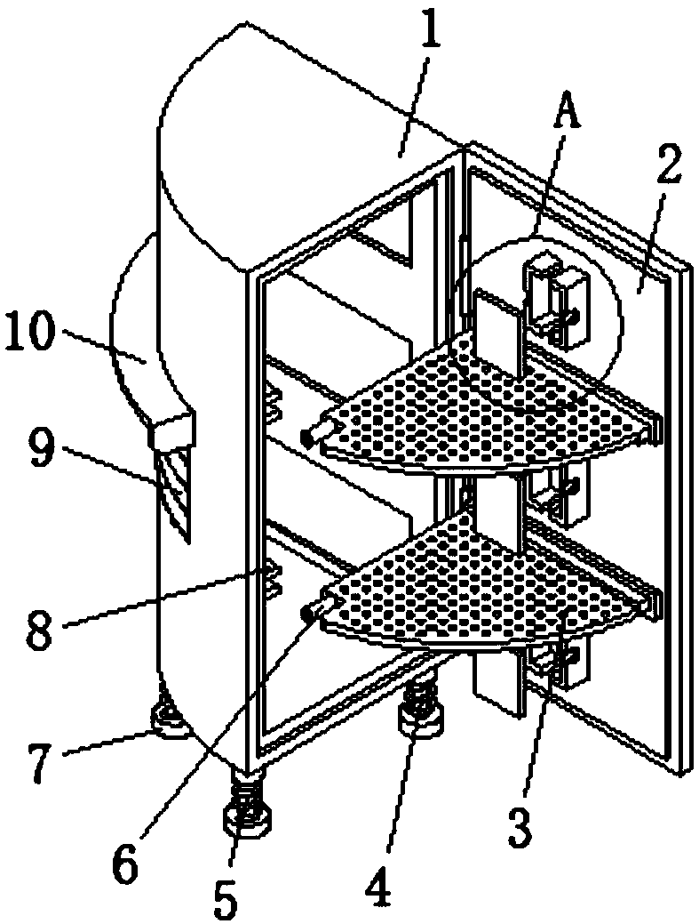
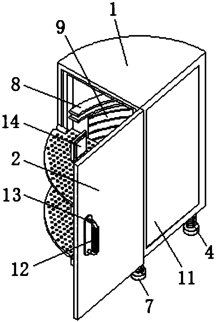
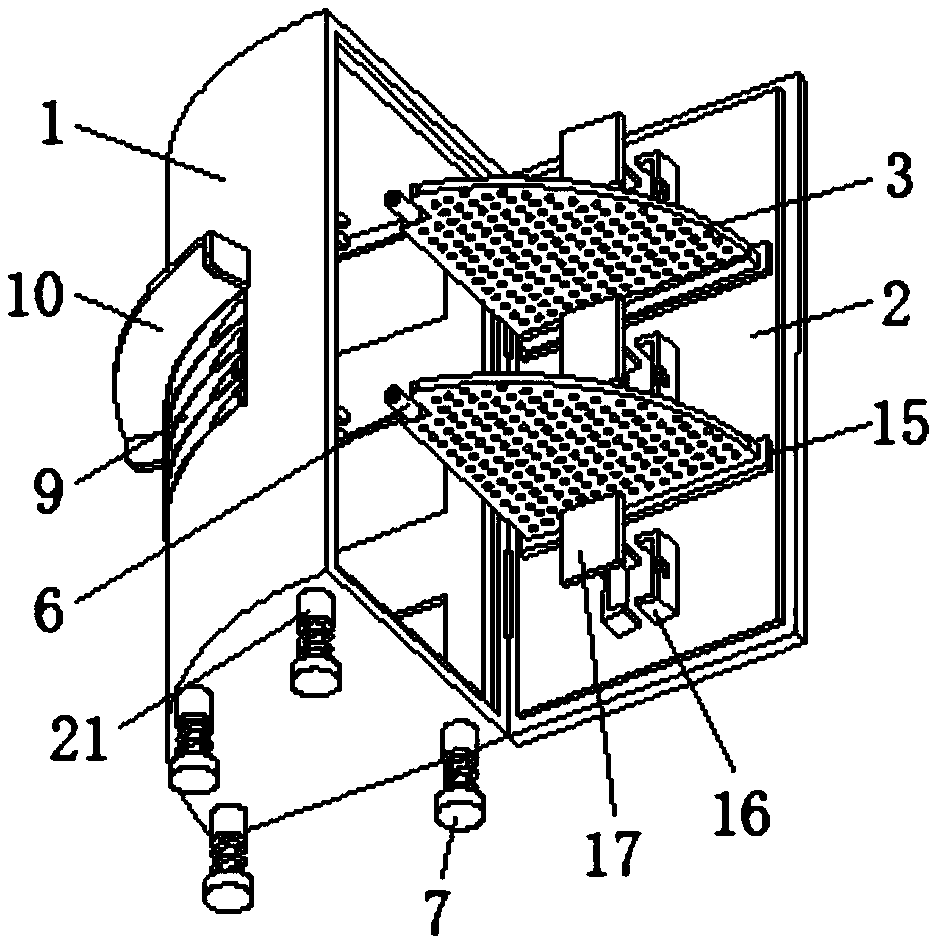
[0023] see Figure 1-Figure 5 As shown, the present invention provides a push-pull mobile power cabinet device, including a fan-shaped cabinet body 1, one side of the fan-shaped cabinet body 1 is connected with a cabinet door 2 through a hinge, and four sets of columns 21 are connected to the lower side of the fan-shaped cabinet body 1 , one side of the fan-shaped cabinet 1 is provided with a transparent plate 11, which is convenient for observing the inside of ...


PUM


Abstract

A push-pull movable power cabinet device include a fan-shaped cabinet, one side of the fan-shaped cabinet body is connected with a cabinet door through a hinge, the lower side of the fan-shaped cabinet body is connected with four groups of upright columns, A side of the cabinet door close to the fan-shaped cabinet body is provided with two sets of connecting bosses symmetrically distributed, A fan-shaped pushing and pulling plate is arranged on the side of the connecting boss away from the cabinet door, the fan-shaped pushing and pulling plates are provided with heat dissipation holes uniformly distributed at equal distances, A side of the sector-shaped cabinet body close to the sector-shaped push-pull plate is provided with a sector-shaped support slide rail, As that fan-shaped push-pullplate is driven to slide in the fan-shaped support slide rail by the rotation of the cabinet door, the electric power equipment inside the power cabinet is convenient to be overhauled and maintained,Springs, sliding columns, anti-skid pads and upright columns are used together to provide better shock absorbing performance, fan blades and heat dissipating holes can improve heat dissipating effectand facilitate external observation, and take-up boxes are convenient for combing electric wires of electric power equipment.

Description

technical field [0001] The invention relates to the field of power cabinet equipment, in particular to a push-pull mobile power cabinet equipment. Background technique [0002] The power cabinet usually consists of a cabinet body and a cabinet door. However, the inside of the conventional power cabinet usually lacks a support frame for the installation of electrical equipment, resulting in insufficient use of the internal space of the power cabinet, and the installation of electrical equipment is cumbersome and disorderly. In the power cabinet, the mounting bracket is usually welded inside the power cabinet, which is not convenient for repairing and maintaining the power equipment inside the power cabinet, and does not have a good shock absorption effect. [0003] In addition, the heat dissipation effect of the existing power cabinets is not good, and the angle of the ventilation fan blades cannot be automatically adjusted through temperature changes. When the altitude of t...

Claims


Application Information

Patent Timeline
IPC IPC(8): H02B1/36H02B1/38H02B1/30H02B1/56H02B1/20H02B1/54
CPCH02B1/36H02B1/20H02B1/202H02B1/30H02B1/303H02B1/306H02B1/38H02B1/54H02B1/565
Inventor 沈晨
Owner 沈晨
Why Eureka
Try Eureka