
Gamepad for Ar imaging technology

A gamepad and technology, which is applied in the field of gamepads for Ar imaging technology, can solve the problems of high requirements on the internal connection system of the gamepad, high cost of the gamepad, and high requirements for the connection system, and achieves a good feel, outstanding operation effect, Highly flexible effect

Inactive Publication Date: 2018-12-21
GANZHOU YANSHUNFEI TECH CO LTD
View PDF7 Cites 0 Cited by
  • Summary
  • Abstract
  • Description
  • Claims
  • Application Information

AI Technical Summary

Problems solved by technology

[0002] The gamepad for Ar imaging technology is a gamepad using Ar imaging technology, including the handle body and Ar imaging technology device. The graphics and models in the game are attached to real objects through computer vision methods, and then displayed through game actions, but In practical application, Ar imaging technology needs to find an attachment plane, and then map the 3D model to the screen, and in the process of connecting information, the requirements for the connection system are too high, it is not easy to map all the models, and the integrity of the model is compromised. to destroy
[0003] However, the existing Ar imaging technology uses the gamepad to display real information and virtual information at the same time, and the two superimpose and synthesize the information, and finally attach it to a surface, and then display it through game actions. However, in actual application Among them, this operation has too high requirements for the internal receiving system of the gamepad, resulting in high cost and complicated internal structure of the gamepad.

Method used


Image

  • Gamepad for Ar imaging technology
  • Gamepad for Ar imaging technology
  • Gamepad for Ar imaging technology

Examples


Embodiment 1

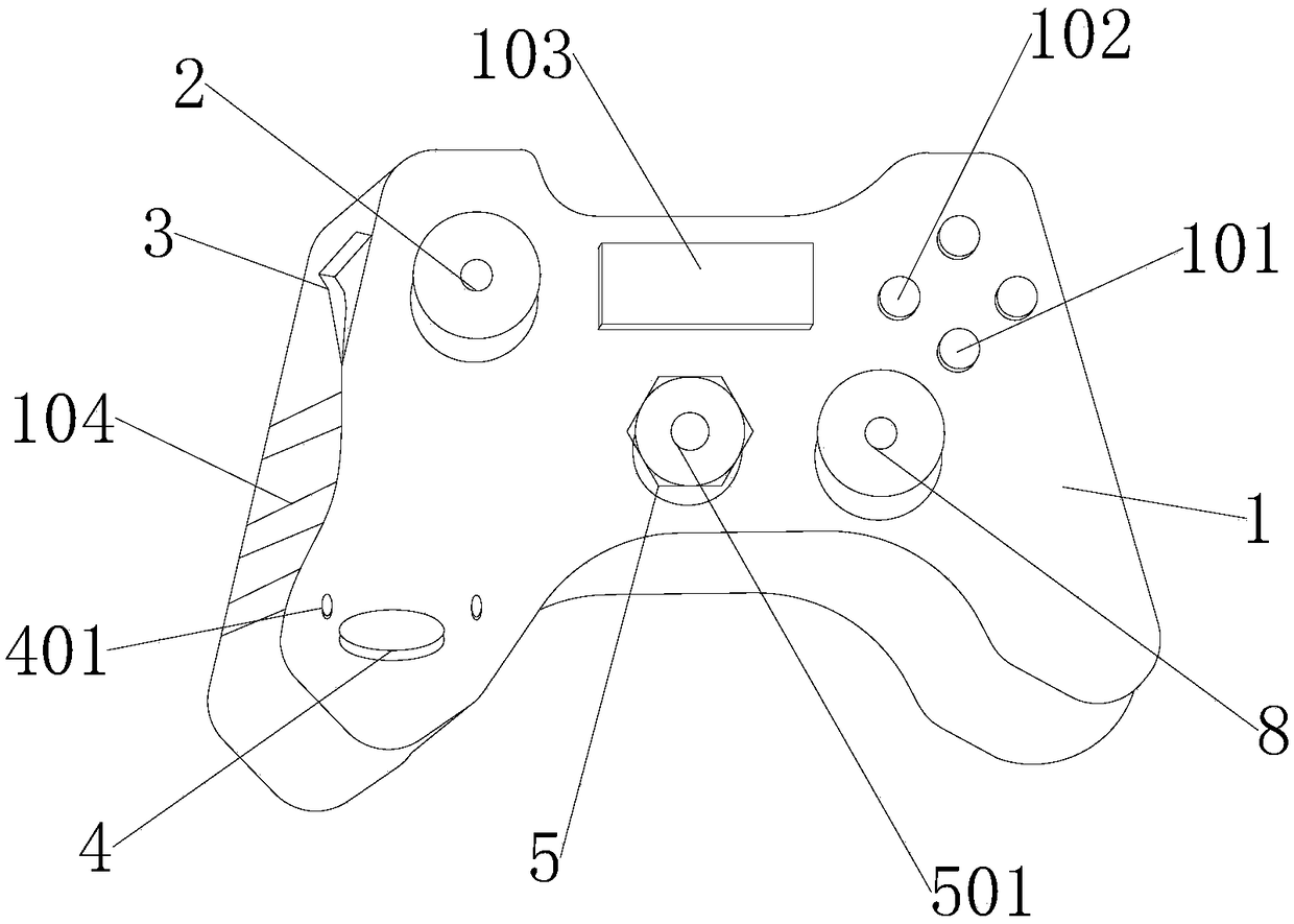
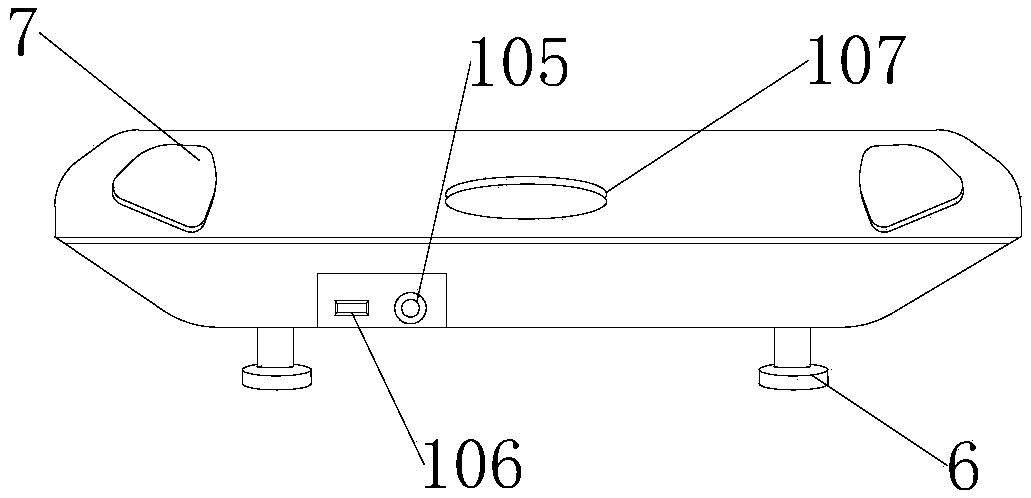
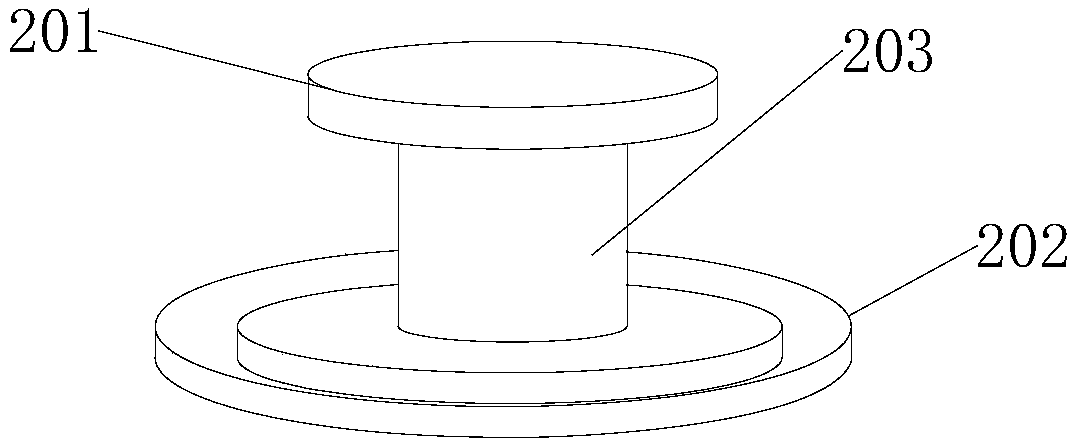
[0028] see Figure 1-4 , the present invention provides a technical solution: a game handle for Ar imaging technology, including a handle body 1, a right rocker 8 and an Ar imaging device 7, a display screen 103 is fixedly installed on the top of the upper surface of the handle body 1, and a display screen 103 is fixedly installed on the handle body 1 The surface is close to the left side of the display screen 103, and the left joystick 2 is movably installed. The wire insertion hole 105 is fixedly installed under the back of the handle body 1. The signal receiving device 107 is fixedly installed on the top of the back of the handle body 1. The top of the left joystick 2 is bonded. There is a handle ring 201, the bottom of the left joystick 2 is fixedly connected with a joystick movable ring 202, the upper surface of the handle body 1 away from the left joystick 2 is fixed with a help key 4, and the bottom of the display screen 103 is movable with a direction key 5 , the inner...

Embodiment 2

[0030] A gamepad for Ar imaging technology, comprising a handle body 1, a right rocker 8 and an Ar imaging device 7, a display screen 103 is fixedly installed on the top of the upper surface of the handle body 1, and the upper surface of the handle body 1 is close to the left side of the display screen 103 The left rocker 2 is movable installed, the wire insertion hole 105 is fixedly installed on the back of the handle body 1, the signal receiving device 107 is fixedly installed on the upper back of the handle body 1, the handle ring 201 is glued on the top of the left rocker 2, and the left rocker 2 The bottom is fixedly connected with the joystick movable ring 202, the upper surface of the handle body 1 away from the left joystick 2 is fixedly installed with the help key 4, and the bottom of the display screen 103 is movablely installed with the direction key 5, and the inner center of the direction key 5 is connected with a BACK key 501, four corners of the bottom of the han...

Embodiment 3

[0033] A gamepad for Ar imaging technology, comprising a handle body 1, a right rocker 8 and an Ar imaging device 7, a display screen 103 is fixedly installed on the top of the upper surface of the handle body 1, and the upper surface of the handle body 1 is close to the left side of the display screen 103 The left rocker 2 is movable installed, the wire insertion hole 105 is fixedly installed on the back of the handle body 1, the signal receiving device 107 is fixedly installed on the upper back of the handle body 1, the handle ring 201 is glued on the top of the left rocker 2, and the left rocker 2 The bottom is fixedly connected with the joystick movable ring 202, the upper surface of the handle body 1 away from the left joystick 2 is fixedly installed with the help key 4, and the bottom of the display screen 103 is movablely installed with the direction key 5, and the inner center of the direction key 5 is connected with a BACK key 501, four corners of the bottom of the han...


PUM


Abstract

The invention discloses a gamepad for an Ar imaging technology. The gamepad comprises a gamepad body, a right rocker and an Ar imaging device; a display screen is fixedly mounted at the top of the upper surface of the gamepad body, and the portion, close to the left side face of the display screen, of the upper surface of the gamepad body is provided with a left rocker; a line insertion hole is fixedly formed in the lower portion of the back of the gamepad body, and a signal receiving device is fixedly mounted at the upper portion of the back of the gamepad body; a gamepad ring is attached tothe top of the left rocker, a rocker moving ring is fixedly connected to the bottom of the left rocker, and a help key is fixedly mounted at the side, away from the left rocker, of the upper surface of the gamepad body. Through the arrangement of the gamepad body, the internal structure of the gamepad can be protected, the external material of the gamepad body belongs to hard materials, the outersurface is smooth, the side face of the gamepad body is provided with a non-slip outer protection layer, the ergonomic contact design is adopted, the gamepad has a sweat absorbing function, is good inhand feel and is not easily sticky to the hands or does not easily get worn due to long-time friction with the hands, and the use time and service life of the gamepad body are prolonged to a certaindegree.

Description

technical field [0001] The invention relates to the technical field of handles, in particular to a game handle for Ar imaging technology. Background technique [0002] The gamepad for Ar imaging technology is a gamepad using Ar imaging technology, including the handle body and Ar imaging technology device. The graphics and models in the game are attached to real objects through computer vision methods, and then displayed through game actions, but In practical application, Ar imaging technology needs to find an attachment plane, and then map the 3D model to the screen, and in the process of connecting information, the requirements for the connection system are too high, it is not easy to map all the models, and the integrity of the model is compromised. to destruction. [0003] However, the existing Ar imaging technology uses the gamepad to display real information and virtual information at the same time, and the two superimpose and synthesize the information, and finally a...

Claims


Application Information

Patent Timeline
Patent Type & Authority Applications(China)
IPC IPC(8): A63F13/24A63F13/92
CPCA63F13/24A63F13/92
Inventor 钟德升
Owner GANZHOU YANSHUNFEI TECH CO LTD
Learn More