Supercharge Your Innovation With Domain-Expert AI Agents!

Positioning tool for installation of pressurization oil cylinder of of rotary drilling rig and installation positioning method

A technology for positioning tooling and pressurized cylinders, applied in the direction of manufacturing tools, workpiece clamping devices, etc., can solve problems such as asymmetry, pressurized cylinder displacement axis, long distance, etc., to improve centering, ensure power transmission, ensure accurate results

Pending Publication Date: 2018-12-21
BEIJING CSR TIMES LOCOMOTIVE & ROLLING STOCK MECHANICS
View PDF0 Cites 0 Cited by
  • Summary
  • Abstract
  • Description
  • Claims
  • Application Information

AI Technical Summary

Problems solved by technology

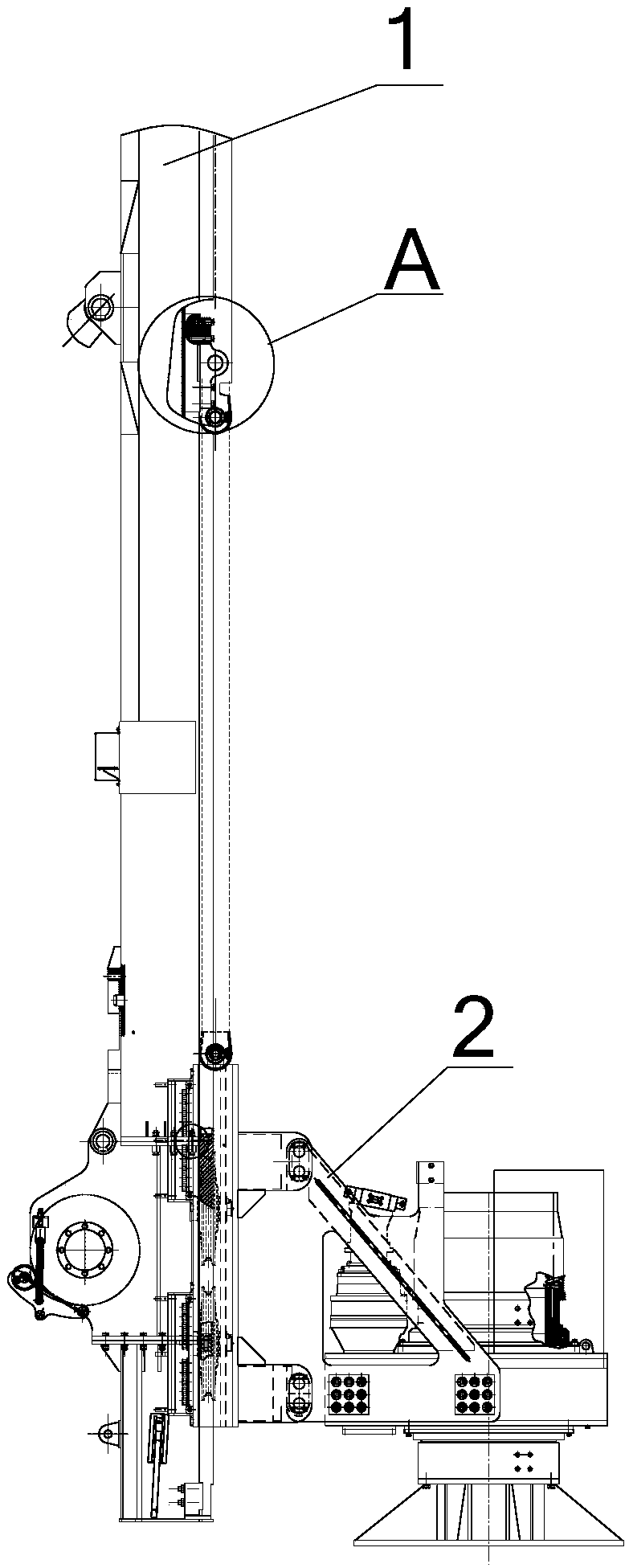
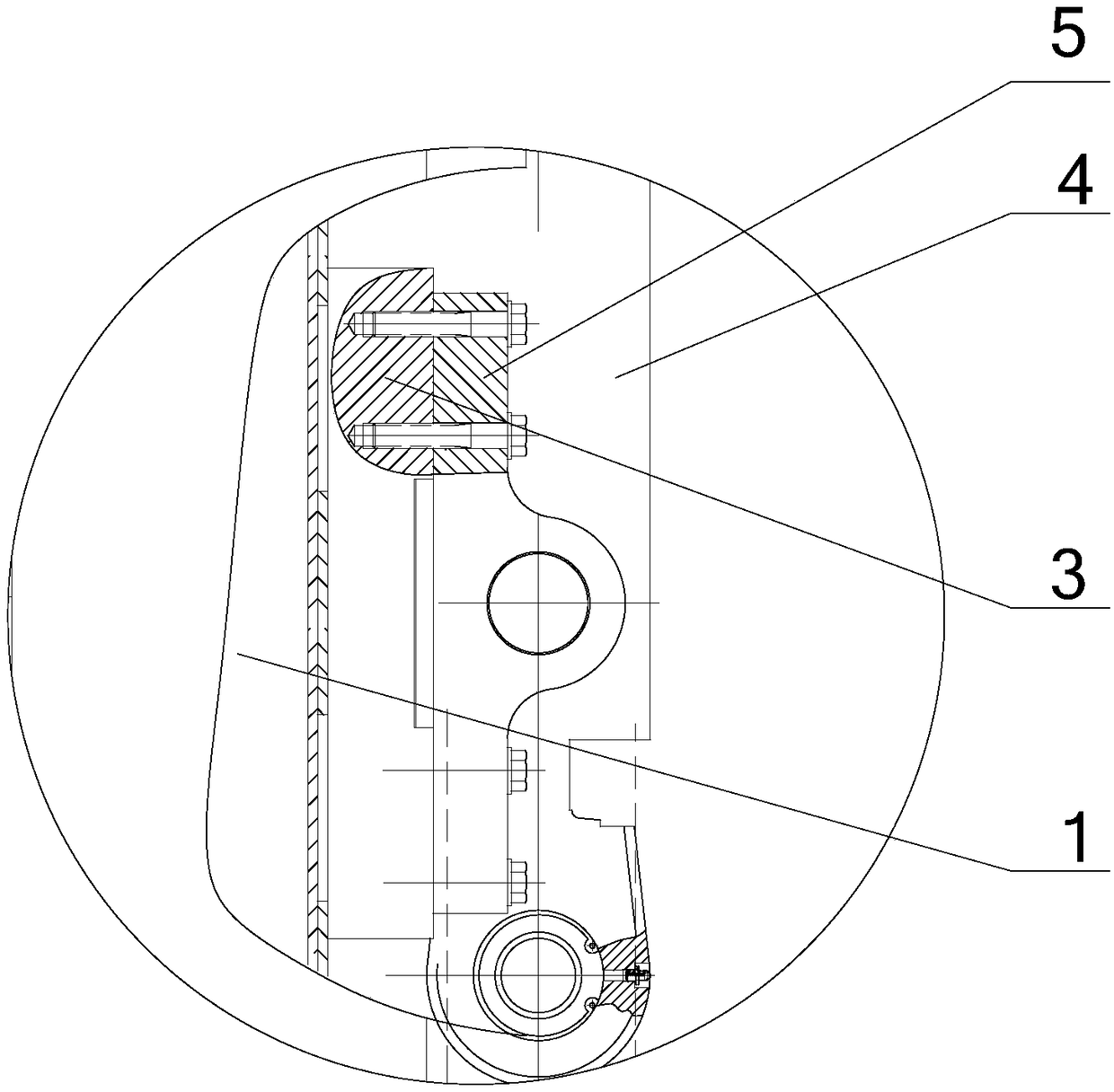
However, due to the welding and assembly of the pressurized cylinder 4, there is no effective reference for the concave wall surface 11 of the mast. After the pressurized cylinder 4 is fixed, because the installation positions of the two cylinders are not easy to locate, resulting in pressurization. The oil cylinder 4 will have a certain displacement and asymmetry of the axis, and the distance between the pressurized oil cylinder 4 and the power head 2 is relatively far, which is prone to problems that the alignment and coaxiality of the axis cannot be guaranteed, resulting in pressurization The oil cylinder 4 cannot be accurately connected to the power head 2, and thus the power transmission cannot be performed accurately, which makes the working device of the rotary drilling rig unable to meet the drilling requirements
[0004] In summary, how to solve the problem of displacement and axis asymmetry in the installation and positioning of the pressurized cylinder on the mast has become an urgent problem to be solved by those skilled in the art

Method used


Image

  • Positioning tool for installation of pressurization oil cylinder of of rotary drilling rig and installation positioning method
  • Positioning tool for installation of pressurization oil cylinder of of rotary drilling rig and installation positioning method
  • Positioning tool for installation of pressurization oil cylinder of of rotary drilling rig and installation positioning method

Examples


Embodiment Construction

[0037] The core of the present invention is to provide a positioning tool for installing the pressurized oil cylinder of the rotary drilling rig, which improves the centering of the pressurized oil cylinder installed on the mast.

[0038] The invention also provides an installation and positioning method using the positioning tool, which improves the centering of the pressurized oil cylinder installed on the mast.

[0039] The following will clearly and completely describe the technical solutions in the embodiments of the present invention with reference to the accompanying drawings in the embodiments of the present invention. Obviously, the described embodiments are only some, not all, embodiments of the present invention. Based on the embodiments of the present invention, all other embodiments obtained by persons of ordinary skill in the art without making creative efforts belong to the protection scope of the present invention.

[0040] Please refer to Figure 5-Figure 9 ,...


PUM


Abstract

The invention discloses a positioning tool for installation of a pressurization oil cylinder of a rotary drilling rig and an installation positioning method. The positioning tool comprises a positioning plate, the positioning plate is provided with a left row of installation holes and a right row of installation holes which are symmetrical left and right relative to the center line of the positioning plate, and the positions of the left row of installation holes are in one-to-one correspondence with the positions of installation holes located in an oil cylinder installation fixing base on theright side of the inner concave wall face of a mast. During installation, one pair of oil cylinder installation fixing bases are fixed to the left row of installation holes and the right row of installation holes in the positioning plate correspondingly, the center line of the positioning plate and the center line of the mast are aligned to coincide, the oil cylinder installation fixing bases arefixed to the inner concave wall face of the mast, finally, the positioning plate is detached from the oil cylinder installation fixing bases, positioning installation of the oil cylinder installationfixing bases is completed, and alignment of the pressurization oil cylinder installed in the follow-up process relative to the mast is ensured.

Description

technical field [0001] The invention relates to the technical field of engineering machinery, in particular to a positioning tool for installing a pressurized oil cylinder of a rotary drilling rig. It also relates to an installation and positioning method using the positioning tool. Background technique [0002] Rotary drilling rig is a kind of construction machine suitable for hole forming in construction foundation engineering. At present, the power head of some mast type rotary drilling rigs is pressurized by oil cylinder, that is, when the power head is outputting power, it needs a pressure to drill. Do effective work. The pressurized oil cylinder is installed on the mast, and the power head is slidably arranged on the mast. The piston rod of the pressurized oil cylinder is connected with the power head through a pin, so that the pressurized oil cylinder provides pressure for the power head to move down the mast. [0003] The pressurized oil cylinder 4 is rigidly conne...

Claims


Application Information

Patent Timeline
IPC IPC(8): B25B11/02
CPCB25B11/02
Inventor 张昊陈曦吴斌李肖彬
Owner BEIJING CSR TIMES LOCOMOTIVE & ROLLING STOCK MECHANICS
Features
  • R&D
  • Intellectual Property
  • Life Sciences
  • Materials
  • Tech Scout
  • Unparalleled Data Quality
  • Higher Quality Content
  • 60% Fewer Hallucinations
Learn More