Improved extruder barrel structure

An improved, extruder technology, applied in the field of extruders, can solve the problems of difficult maintenance, high manufacturing cost, resin mixing, etc., and achieve the effect of simple and convenient assembly and maintenance, simple manufacturing process, and improved rigidity

Pending Publication Date: 2018-12-21
GOLD CUP ELECTRIC APP HENGYANG CABLES
View PDF0 Cites 2 Cited by
  • Summary
  • Abstract
  • Description
  • Claims
  • Application Information

AI Technical Summary

Problems solved by technology

However, the structure of the barrel hopper cooling part of this structure is cumbersome, the manufacturing cost is high, and the maintenance is difficult
Moreover, the gap between the forced feeding sleeve 3 and the inner wall of the barrel 1 is connected by a welding structure 7. Once the welding is not tight, the processed resin is easily mixed into the cooling circulating water, which affects the use of the equipment.

Method used


Image

  • Improved extruder barrel structure
  • Improved extruder barrel structure

Examples


Embodiment Construction

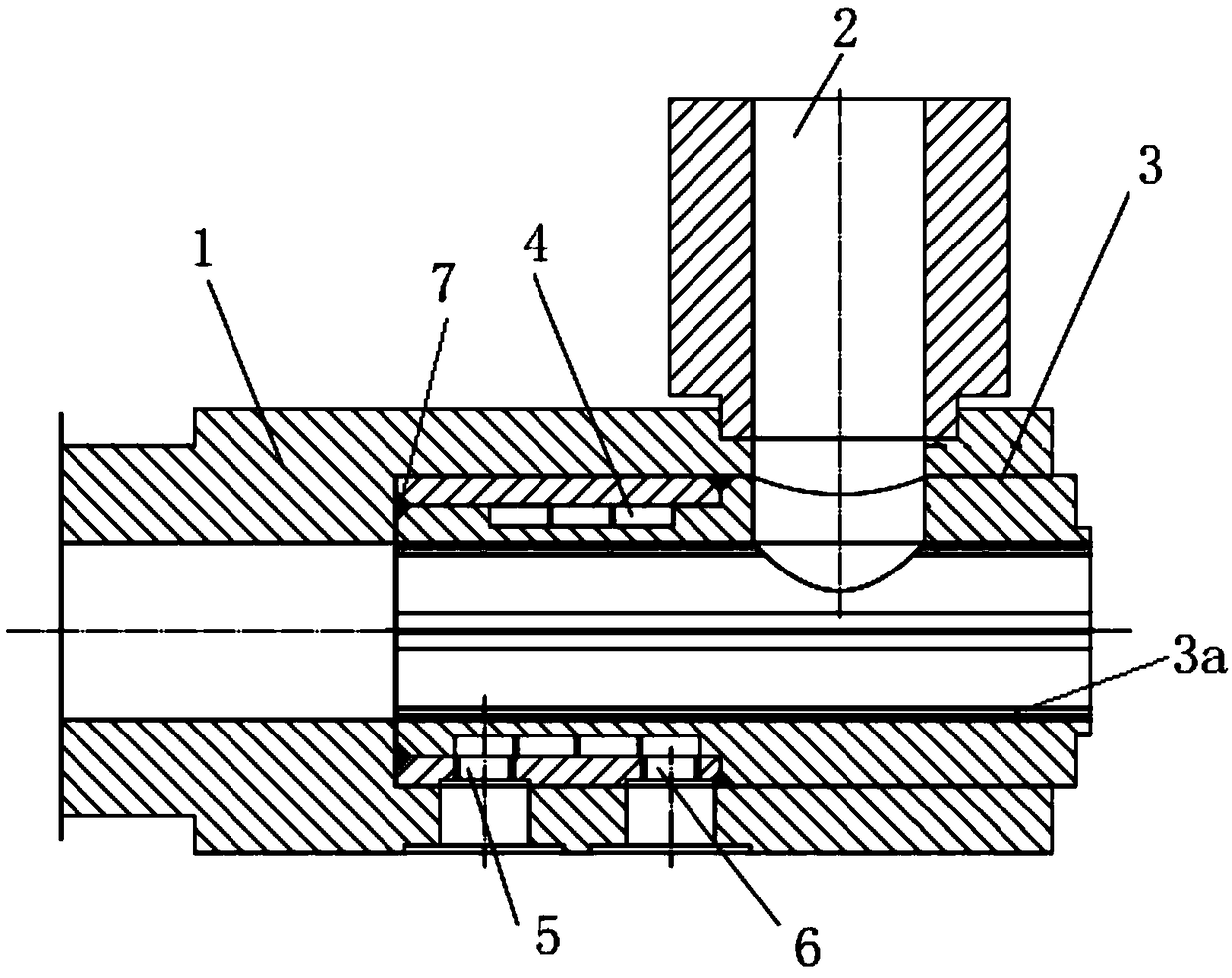
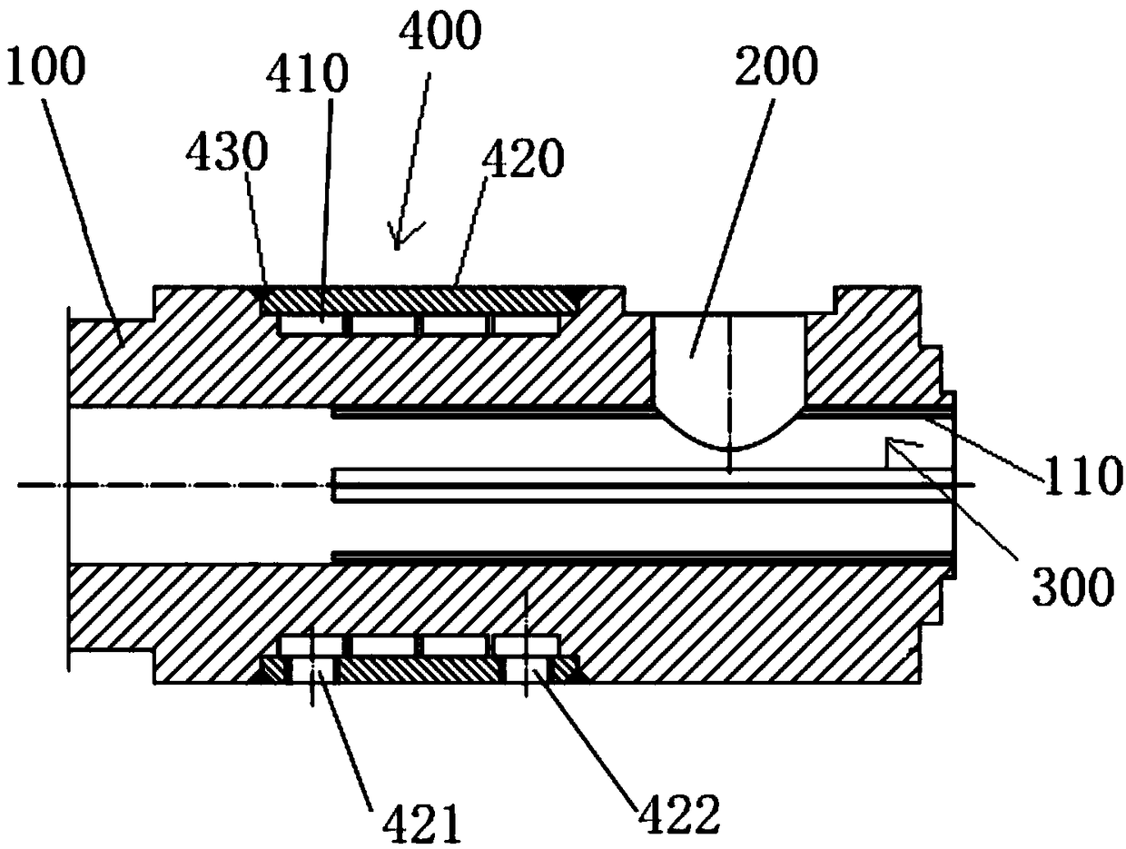
[0015] see figure 2 The improved structure of the extruder barrel shown includes a barrel 100, the outer wall of the barrel 100 is connected with a material inlet 200, and the inner wall of the barrel 100 is circumferentially arranged with a number of concave strips 110 at intervals to form a forced feeding The sleeve 300 , the feed inlet 200 is in communication with the forced feeding sleeve 300 , and the outer wall of the barrel 100 is also provided with a cooling water channel 400 .

[0016] In this embodiment, the outer wall of the barrel 100 is provided with an annular cooling water tank 410, and the annular cooling water tank 410 is covered by an annular wrapping 420. The annular wrapping 420 is provided with a water inlet 421 and a water outlet 422. The side 420 forms the cooling water channel 400 . The gap between the annular cooling water tank 410 and the annular wrapping 420 is sealed by a welding structure 430 .

[0017] The beneficial effects of the present inve...


PUM


Abstract

The invention discloses an improved extruder barrel structure. The improved extruder barrel structure comprises a barrel, wherein the outer wall of the barrel is connected with a feeding opening, a plurality of internally concave stripes are arranged on the inner wall of the barrel in the peripheral direction at intervals so as to form a forced feeding sleeve, the feeding opening communicates withthe forced feeding sleeve, and a cooling water runner is further arranged on the outer wall of the barrel. The improved extruder barrel structure has the beneficial effects that 1, the forced feedingpart of the barrel and the barrel are made into a whole, so that the rigidity of the barrel is improved, and manufacture chains are simpler and more convenient; 2, the cooling water runner is fully isolated from the forced feeding sleeve, so that processed resin cannot be mixed with cooling circulating water; 3, the circulating cooling part of a hopper is arranged in the barrel body, only the opening position of a water inlet and outlet pipe slightly changes, and the appearance of the original equipment is not affected; 4, and the assembly and maintenance of the barrel are simpler and more convenient to that of the original structure.

Description

technical field [0001] The invention relates to the technical field of extruders, in particular to an improved structure of a φ60 extruder barrel of a 110KV production line imported from Germany. Background technique [0002] see figure 1 , the original German imported 110KV production line φ60 barrel 1 is embedded with a forced feeding sleeve 3 in the middle of one end, and the outer wall of the barrel 1 is connected with a feed inlet 2 connected with the inner cavity of the forced feeding sleeve 3, and the forced feeding sleeve 3 is connected to the machine. A cooling water channel 4 is provided between the inner walls of the cylinder 1 , and a number of inner concave strips 3 a are arranged at circumferential intervals on the inner wall of the forced feeding sleeve 3 , and the cooling water channel 4 has a water inlet 5 and a water outlet 6 . However, the structure of the barrel hopper cooling part of this structure is relatively cumbersome, the manufacturing cost is hig...

Claims


Application Information

Patent Timeline
Patent Type & Authority Applications(China)
IPC IPC(8): B29C47/66B29C47/80B29C47/10
Inventor 艾卫民吴兴君侯雯馨
Owner GOLD CUP ELECTRIC APP HENGYANG CABLES
Why Eureka
Try Eureka