Manipulator for bottle blowing machine

A technology of manipulators and bottle blowing machines, applied in the field of manipulators, can solve problems such as inability to accurately discharge bottles, clamp head 3 stuck, and inability to accurately align the host machine, etc.

Pending Publication Date: 2018-12-21
WUXI XINGUANG COMP INSTALLATION
View PDF0 Cites 0 Cited by
  • Summary
  • Abstract
  • Description
  • Claims
  • Application Information

AI Technical Summary

Problems solved by technology

[0005] However, when the jig head 3 is controlled by the adjustment cylinder 5, when the action of the adjustment cylinder 5 is delayed, it is easy to cause the jig head 3 to be stuck close to the edge of the abutment 1, or it is far away from the edge of the abutment 1 and cannot be accurately aligned with the next process. bit of the host, or can not be accurately out of the bottle

Method used


Image

  • Manipulator for bottle blowing machine
  • Manipulator for bottle blowing machine
  • Manipulator for bottle blowing machine

Examples


Embodiment 1

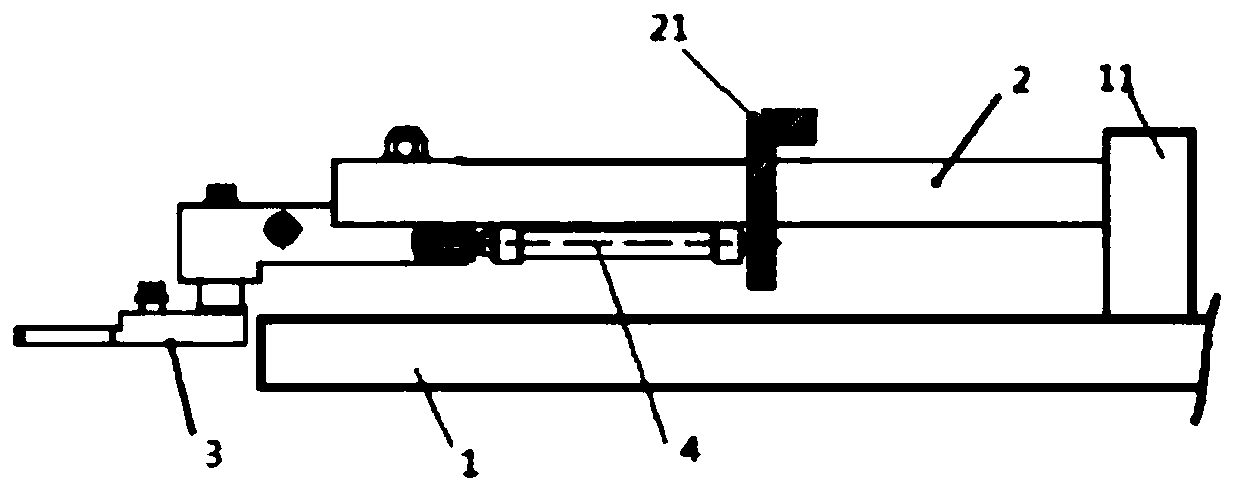
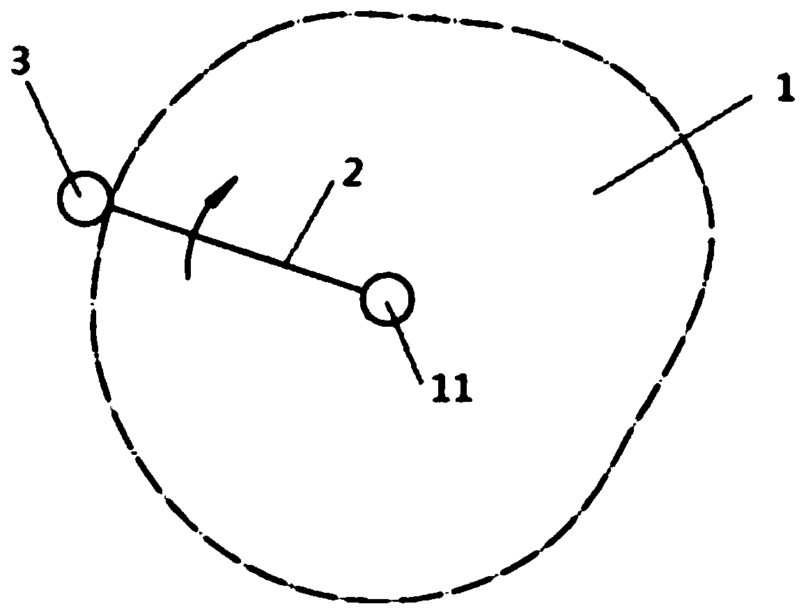
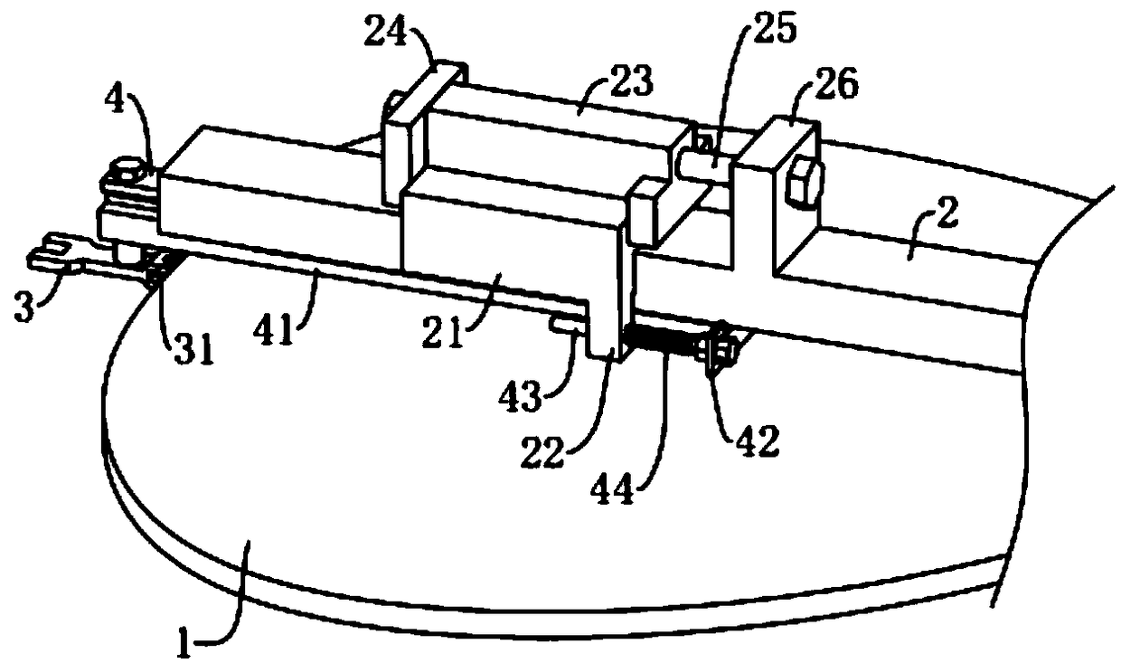
[0026] The structure of a robot arm for a bottle blowing machine provided in this embodiment is shown in the figure.

[0027] The manipulator for a bottle blowing machine includes a central rotating shaft 11 arranged on the base 1, a rotating arm 2 controlled by the central rotation, and a clamp head 3 arranged at the end of the rotating arm 2. The rotating arm 2 corresponds to the base One end of table 1 edge is provided with slideway 28, and slideway 28 extends toward central rotating shaft 11 places along the length direction of rotating arm 2, and sliding block 4 is slidably connected in slideway 28, and fixture head 3 is arranged on sliding block 4, and rotating arm 2 is provided with a connecting frame 21, the connecting frame 21 and the slider 4 are connected by an elastic member 44, the elastic member 44 is in a state of elastic deformation, and in the process of restoring the elastic member 44 to its original shape, it drives the sliding block 4 close to the central sh...


PUM


Abstract

The invention discloses a manipulator for a bottle blowing machine, and relates to the technical field of manipulators. The manipulator for the bottle blowing machine comprises a central rotating shaft arranged on the base platform, a rotating arm controlled by the central rotating shaft, and a clamp head arranged at the end of the rotating arm. A slideway is formed in one end, corresponding to the edge of the base platform, of the rotating arm; the slideway extends to the central rotating shaft along the length direction of the rotating arm; a sliding block is slidably connected in the slideway; and the clamp head is arranged on the sliding block. A connecting frame is arranged on the rotating arm; the connecting frame and the sliding block are connected through an elastic piece; and theelastic piece is in an elastic deformation state. The elastic piece drives the sliding block to slide close to the central rotating shaft, so that the clamp head is attached to the edge of the base platform in the process of returning to the original state. According to the manipulator for the bottle blowing machine, the elastic piece is used for replacing an adjusting air cylinder, so that the clamp head has flexibility and is not prone to jamming when moving along the edge of the base platform.

Description

technical field [0001] The invention relates to the field of manipulators, in particular to a manipulator for bottle blowing machines. Background technique [0002] When the blow molding machine is working, the preform or bottle needs to be transferred by the manipulator from the heating machine to the main machine, and then from the main machine to the bottle output. [0003] Such as figure 1 with figure 2 As shown, the manipulator includes a clamp head 3 located at one end of the rotating arm 2 , and the other end of the rotating arm 2 is connected to the base 1 through a central rotating shaft 11 . The central rotating shaft 11 drives the jig head 3 to move along the edge of the abutment 1 . The clamp head 3 is controlled by the adjustment cylinder 5 to slide along the length direction of the rotating arm 2 . [0004] Since the base 1 is in the shape of a cam, in order to keep the jig head 3 moving against the edge of the boss, it is necessary to adjust the cylinder ...

Claims


Application Information

Patent Timeline
IPC IPC(8): B29C49/42B29L22/00
CPCB29C49/4205B29L2031/7158
Inventor 曲东娜
Owner WUXI XINGUANG COMP INSTALLATION
Why Eureka
Try Eureka