A creep-proof and step-triggered nested rail vehicle end energy absorbing structure
An energy-absorbing structure and rail vehicle technology, which is applied in railway car body parts, railway vehicle wheel guards/buffers, transportation and packaging, etc. problems, to achieve the effect of easy and orderly crushing, reducing the peak collision force, and saving costs
- Summary
- Abstract
- Description
- Claims
- Application Information
AI Technical Summary
Problems solved by technology
Method used
Image

Examples
Embodiment Construction
[0032] The present invention will be described in further detail below in conjunction with the accompanying drawings and embodiments.
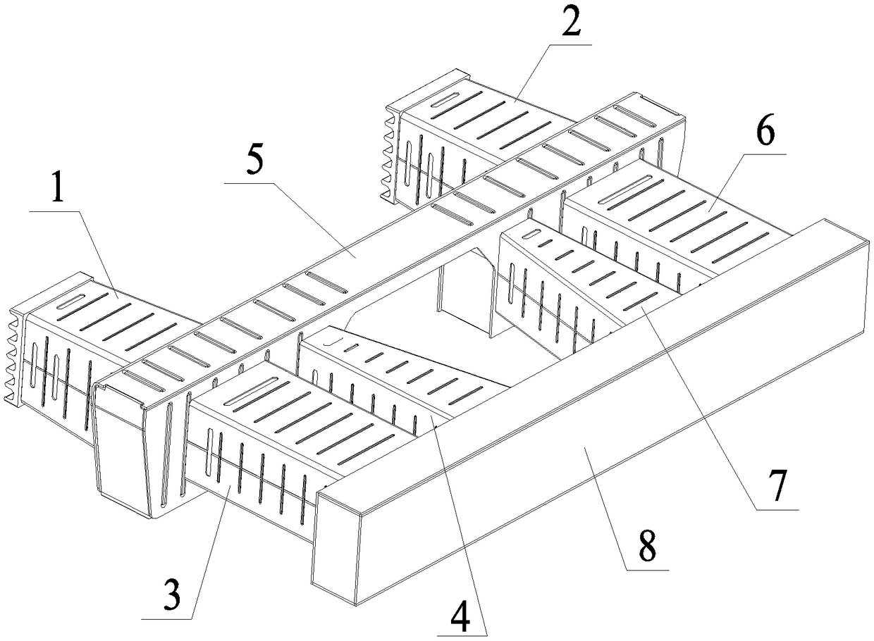
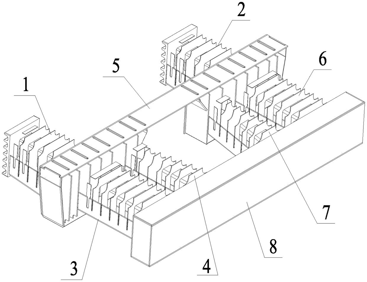
[0033] Such as figure 1 and figure 2 As shown, the anti-climbing and hierarchical triggering nested rail vehicle end energy-absorbing structure of the present invention includes a primary energy-absorbing structure, a secondary energy-absorbing structure, a connecting beam structure 5 and a rear end support beam 8, and the primary energy-absorbing structure The energy structure includes an energy-absorbing structure 1 with anti-climbing teeth on one side and an energy-absorbing structure 2 with anti-climbing teeth on two sides. Variable cross-section box-type energy-absorbing structure 4, two-position side equal-section box-type energy-absorbing structure 6 and two-position side variable-section box-type energy-absorbing structure 7; The structure of the energy-absorbing structure 2 of climbing teeth is exactly the same, the ends of the ene...
PUM
 Abstract
Description
Claims
Application Information
 - Generate Ideas
- Intellectual Property
- Life Sciences
- Materials
- Tech Scout
- Unparalleled Data Quality
- Higher Quality Content
- 60% Fewer Hallucinations
Browse by: Latest US Patents, China's latest patents, Technical Efficacy Thesaurus, Application Domain, Technology Topic, Popular Technical Reports.
© 2025 PatSnap. All rights reserved.Legal|Privacy policy|Modern Slavery Act Transparency Statement|Sitemap|About US| Contact US: help@patsnap.com