Assembling type lifting device for building

A lifting device, construction technology, applied in the direction of lifting device, lifting frame, spring/shock absorber, etc., can solve the problems of lowering lifting device, not enough safety and reliability, not enough convenience and speed, to improve accuracy, good function, Avoid the effect of excessive lifting error

Inactive Publication Date: 2018-12-21
威海君祥企业管理咨询有限公司
View PDF5 Cites 12 Cited by
  • Summary
  • Abstract
  • Description
  • Claims
  • Application Information

AI Technical Summary

Problems solved by technology

[0004] Aiming at the deficiencies of the prior art, the present invention provides a lifting device for a prefabricated building, which solves the problem that the lifting device for a prefabricated building is difficult to we...

Method used


Image

  • Assembling type lifting device for building
  • Assembling type lifting device for building
  • Assembling type lifting device for building

Examples


Embodiment 1

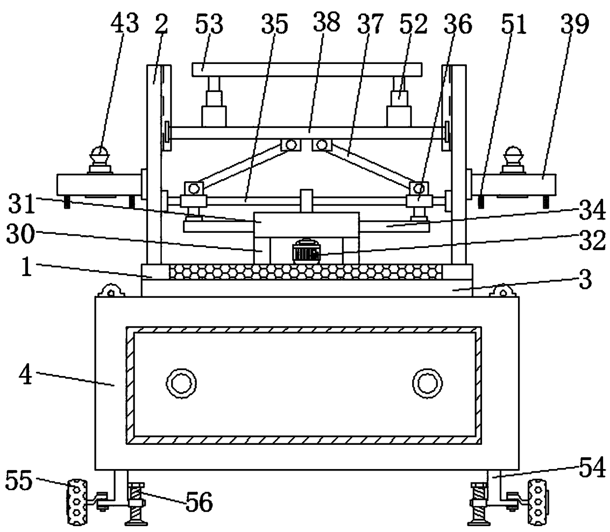
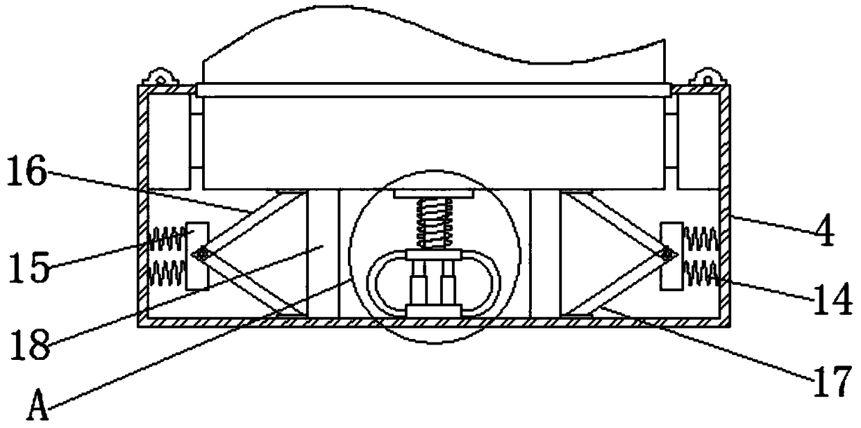
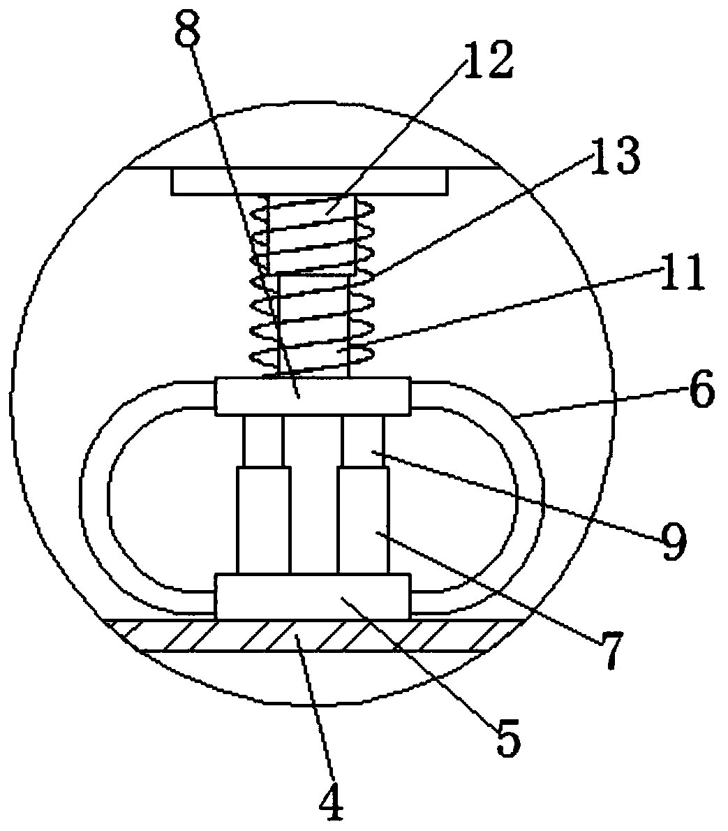
[0037] A lifting device for a prefabricated building, comprising a bottom plate 1, load-bearing vertical plates 2 are fixedly connected to both sides of the top of the bottom plate 1, a heat dissipation box 3 is fixedly connected to the bottom of the bottom plate 1, and a shock absorber is fixedly connected to the bottom of the heat dissipation box 3 Box 4, the bottom of the shock absorbing box 4 cavity is fixedly connected with a support plate 5, both sides of the support plate 5 are fixedly connected with a shock absorbing circular arc plate 6, and both sides of the top of the support plate 5 are fixedly connected with an air cylinder 7, The side of the shock-absorbing circular arc plate 6 away from the support plate 5 is fixedly connected with a fixed plate 8, and both sides of the bottom of the fixed plate 8 are fixedly connected with a piston rod 9, and the bottom end of the piston rod 9 runs through the air cylinder 7 and extends to the air cylinder 7 and the piston rod 9...

Embodiment 2

[0040] A lifting device for a prefabricated building, comprising a bottom plate 1, load-bearing vertical plates 2 are fixedly connected to both sides of the top of the bottom plate 1, a heat dissipation box 3 is fixedly connected to the bottom of the bottom plate 1, and a shock absorber is fixedly connected to the bottom of the heat dissipation box 3 Box 4, the bottom of the shock absorbing box 4 cavity is fixedly connected with a support plate 5, both sides of the support plate 5 are fixedly connected with a shock absorbing circular arc plate 6, and both sides of the top of the support plate 5 are fixedly connected with an air cylinder 7, The side of the shock-absorbing circular arc plate 6 away from the support plate 5 is fixedly connected with a fixed plate 8, and both sides of the bottom of the fixed plate 8 are fixedly connected with a piston rod 9, and the bottom end of the piston rod 9 runs through the air cylinder 7 and extends to the air cylinder 7 and the piston rod 9...


PUM


Abstract

The invention discloses an assembling type lifting device for building. The assembling type lifting device for building comprises a bottom plate, wherein vertical plates are fixedly connected to two sides of the top part of the bottom plate; a heat radiating tank is fixedly connected to the bottom part of the bottom plate; a shock absorption box is fixedly connected to the bottom part of the heatradiating tank; a support plate is fixedly connected to the bottom part of an inner cavity of the shock absorption box; shock absorption circular arc plates are fixedly connected to two sides of the support plate; and air cylinders are fixedly connected to two sides of the top part of the support plate. The assembling type lifting device for building relates to the technical field of building andcan be used for absorbing shock generated when the lifting device lifts up and lowers down, so that the accuracy of the lifting device when lifting up and lowering down is greatly improved, the lifting-lowering error of the lifting device is prevented from being excessive, and the assembling type lifting device for building is safe and reliable; and the device has a good shock absorption functionand a good fixing function, has a good stabilizing function and a heat radiating effect, has a lighting function and a high safety performance, is convenient and fast, and has good convenience.

Description

technical field [0001] The invention relates to the technical field of buildings, in particular to a lifting device for a prefabricated building. Background technique [0002] Buildings assembled from prefabricated parts and components on site are called prefabricated buildings. According to the form and construction method of prefabricated components, they can be divided into five types: block building, plate building, box building, skeleton plate building and rising plate building. The appearance of the early prefabricated buildings was relatively rigid and stereotyped. Later, people improved the design, increasing flexibility and diversity, so that the prefabricated buildings can not only be built in batches, but also have rich styles. There is a mobile home in the United States. , is a relatively advanced prefabricated building. Each residential unit is like a large trailer. It only needs to be pulled to the site by a special car, and then hoisted by a crane to the floor...

Claims


Application Information

Patent Timeline
IPC IPC(8): B66F7/06B66F7/12B66F7/28F16F15/04F16F15/023
Inventor 李晓林
Owner 威海君祥企业管理咨询有限公司
Why Eureka
Try Eureka