Electrolytic plate barrel plating device facilitated taking and discharging materials

An electrolytic plate, picking and discharging technology, applied in the electrolytic process, electrolytic components, etc., can solve the problems of not being able to meet modern production, increase the working time of users, increase the working intensity of users, etc., to increase capacity and save a lot of time , the effect of improving efficiency

Inactive Publication Date: 2018-12-21
十堰市协兴工贸股份有限公司
View PDF0 Cites 0 Cited by
  • Summary
  • Abstract
  • Description
  • Claims
  • Application Information

AI Technical Summary

Problems solved by technology

[0002] Barrel plating is a method of placing a certain number of small parts in a special drum and depositing various metal or alloy coatings on the surface of the parts in a rolling state in an indirect conductive manner to achieve surface protection, decoration and various functional purposes. The electroplating processing method, some barrel plating devices on the market have some defects, which cannot solve the problems encountered in the actual barrel plating well. It is inconvenient to take out components, which increases the working intensity of the user, increases the working time of the user, reduces the working efficiency of the device, and cannot meet the needs of modern production

Method used


Image

  • Electrolytic plate barrel plating device facilitated taking and discharging materials
  • Electrolytic plate barrel plating device facilitated taking and discharging materials
  • Electrolytic plate barrel plating device facilitated taking and discharging materials

Examples


Embodiment Construction

[0021] The following will clearly and completely describe the technical solutions in the embodiments of the present invention with reference to the accompanying drawings in the embodiments of the present invention. Obviously, the described embodiments are only some, not all, embodiments of the present invention.

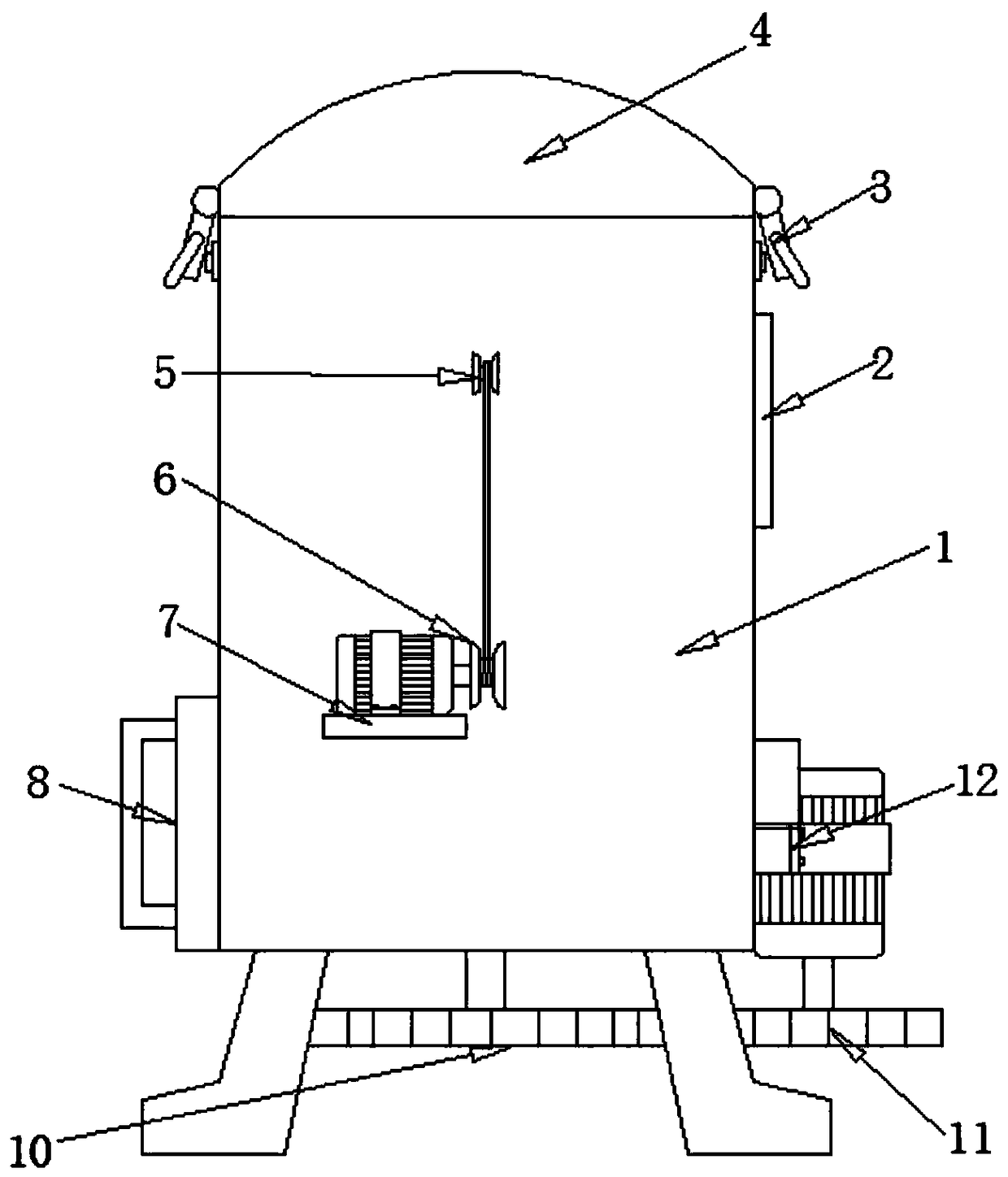
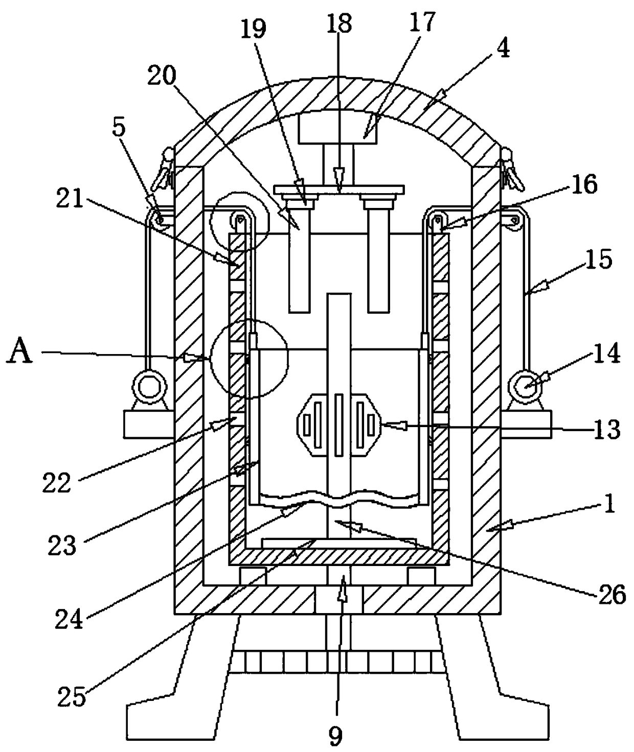
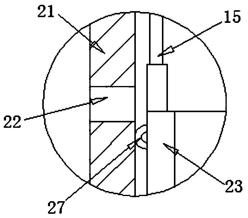
[0022] refer to Figure 1-4 , an electrolytic plate barrel plating device that is convenient for taking and discharging materials, comprising an electroplating box 1 and a retrieving net bucket 23, a stirring motor 12 is fixed on the outer wall of one side of the electroplating box 1 by bolts, and the output shaft of the stirring motor 12 is welded with a first gear 11. There is a groove at the bottom of the electroplating box 1, and the groove is welded with a bearing 9, and the inner wall of the bearing 9 is welded with a vertical transmission rod 26, and the end of the transmission rod 26 located on the outer wall of the electroplating box 1 is welded with a second...


PUM


Abstract

The invention discloses an electrolytic plate barrel plating device facilitated taking and discharging materials. The electrolytic plate barrel plating device includes an electroplating box and a material taking net barrel, wherein the outer wall of one side of the electroplating box is fixed with a stirring motor through bolts, and an output shaft of the stirring motor is welded with a first gear; the bottom of the electroplating box is provided with a groove, and the groove is welded with a bearing; the inner wall of the bearing is welded with a vertically placed transmission rod, the end, on the outer wall of the electroplating box, of the transmission rod is welded with a second gear, the outer wall of one side of the transmission rod is welded with an electroplating cylinder with thematched specification, and the outer wall of the electroplating cylinder is provided with through holes distributed at equal distance; and the inner wall of the bottom of the electroplating cylinder is provided with an electroplating box, and the outer wall of the electroplating box is provided with a cathode plate. According to the electrolytic plate barrel plating device facilitated taking and discharging materials, the material taking net barrel is pulled up through inhaul cables, material taking and discharging of the electrolytic plate barrel plating device is convenient, at the same time, dispersion blades rotate with rotation of the transmission rod to disperse metal elements, dispersion grooves increase the flowing space of electroplating liquid, and the high efficiency of electroplating of the electrolytic plate barrel plating is improved.

Description

technical field [0001] The invention relates to the technical field of electrolytic plate barrel plating, in particular to an electrolytic plate barrel plating device which is convenient for picking and discharging materials. Background technique [0002] Barrel plating is a method of placing a certain number of small parts in a special drum and depositing various metal or alloy coatings on the surface of the parts in a rolling state in an indirect conductive manner to achieve surface protection, decoration and various functional purposes. The electroplating processing method, some barrel plating devices on the market have some defects, which cannot solve the problems encountered in the actual barrel plating well. It is inconvenient to take out components, which increases the working intensity of the user, increases the working time of the user, reduces the working efficiency of the device, and cannot meet the needs of modern production. Contents of the invention [0003]...

Claims


Application Information

Patent Timeline
IPC IPC(8): C25D17/18
CPCC25D17/18
Inventor 张辉华裴虎陈立学袁铭张欢
Owner 十堰市协兴工贸股份有限公司
Why Eureka
Try Eureka