
Thread cleaning device for embroidery machine

A technology for cleaning devices and embroidery machines, which is applied to the mechanism of embroidery machines, embroidery machines, auxiliary devices, etc., to achieve the effects of reducing abnormal operation, convenient centralized cleaning, and prolonging working time

Active Publication Date: 2020-04-03
杭州庄氏布业有限公司
View PDF2 Cites 0 Cited by
  • Summary
  • Abstract
  • Description
  • Claims
  • Application Information

AI Technical Summary

Problems solved by technology

[0006] In view of the deficiencies in the prior art, the object of the present invention is to provide a thread end cleaning device for an embroidery machine. The collection tank can collect the cut thread ends, so that it is convenient for the operator to centrally clean the thread ends, and reduce the thread ends from being squeezed into the knife holder and the machine. Probability of malfunction due to gap between fixed knives

Method used


Image

  • Thread cleaning device for embroidery machine
  • Thread cleaning device for embroidery machine
  • Thread cleaning device for embroidery machine

Examples


Embodiment Construction

[0042]The technical solutions of the present invention will be clearly and completely described below in conjunction with the accompanying drawings. Apparently, the described embodiments are only some of the embodiments of the present invention, not all of them. Based on the embodiments of the present invention, all other embodiments obtained by persons of ordinary skill in the art without making creative efforts fall within the protection scope of the present invention.

[0043] In the description of the present invention, it should be noted that the terms "center", "upper", "lower", "left", "right", "vertical", "horizontal", "inner", "outer" etc. The indicated orientation or positional relationship is based on the orientation or positional relationship shown in the drawings, and is only for the convenience of describing the present invention and simplifying the description, rather than indicating or implying that the referred device or element must have a specific orientation...


PUM


Abstract

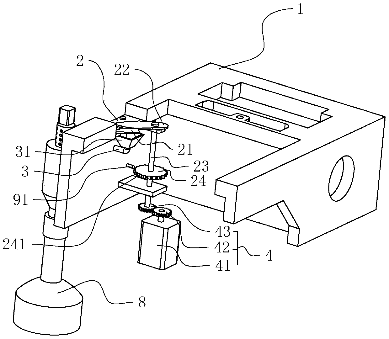
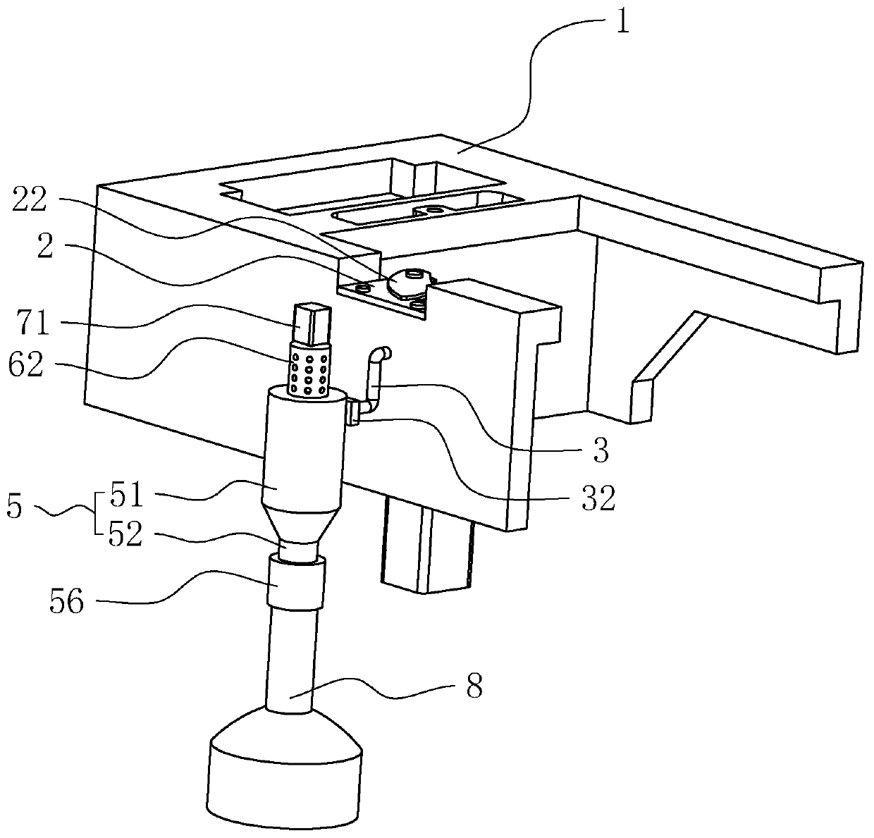
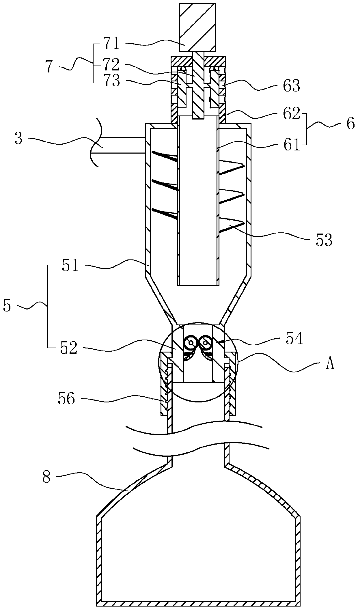
The invention discloses a thread residue cleaning device of an embroidery machine, and relates to the technical field of computer embroidery machines. The thread residue cleaning device comprises a rotating shuttle box body, wherein an installation knife holder is fixedly arranged on the rotating shuttle box body and is connected with a fixed knife and a movable knife; a rotary shaft penetrates through the movable knife; the rotating shuttle box body is connected with a drive assembly; an air intake pipe and a separating cylinder are arranged on the rotating shuttle box body; one end of the air intake pipe is connected with the circumference wall, near the upper end, of the separating cylinder in a tangential way, and the other end of the air intake pipe is positioned under the movable knife; a fan is arranged on the air intake pipe; the lower end of the separating cylinder is detachably connected with a collecting tank; a separating pipe is arranged in the separating cylinder, and iscoaxial with the separating cylinder; the upper end of the separating pipe penetrates out of the separating cylinder; a speed measuring rotary wheel is fixedly sheathed on the rotary shaft; a controlcircuit is arranged on the rotating shuttle box body, and is used for detecting the rotation speed of the speed measuring rotary wheel to control the working of the fan. The thread residue cleaning device has the advantage that the collecting tank is used for collecting the sheared thread residues, so as to facilitate an operator to clean the thread residues, and reduce the probability of abnormalrunning due to extrusion of the thread residues into a gap between the knife holder and the fixed knife.

Description

technical field [0001] The invention relates to the technical field of computerized embroidery machines, in particular to a thread end cleaning device for an embroidery machine. Background technique [0002] Computerized embroidery machine is a machine that uses embroidery threads to embroider patterns on fabrics. The patterns with rich content are embroidered by embroidery threads of different colors. In the process of embroidering this type of pattern, it is often necessary to switch between embroidery threads of different colors. When the embroidery thread is switched, the embroidery thread of the previous color needs to be cut off. If the mode of manual cutting is adopted, the working efficiency of the embroidery machine is low, and the labor intensity of the operator is high. Therefore, automatic thread trimmer is all provided with on the existing most computerized embroidery machines. [0003] The application announcement number is CN105544109A, an automatic thread t...

Claims


Application Information

Patent Timeline
Patent Type & Authority Patents(China)
IPC IPC(8): D05C11/22D05C13/00
CPCD05C11/22D05C13/00
Inventor 庄静松
Owner 杭州庄氏布业有限公司
Learn More