
Novel integrated ceiling electric appliance

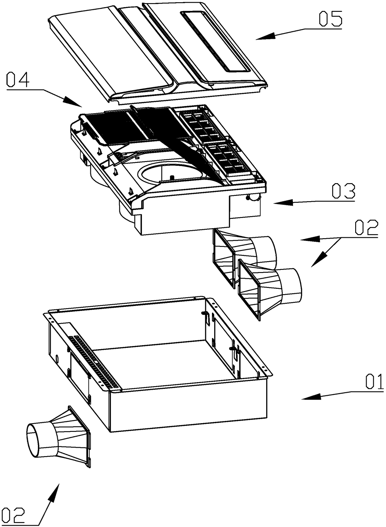
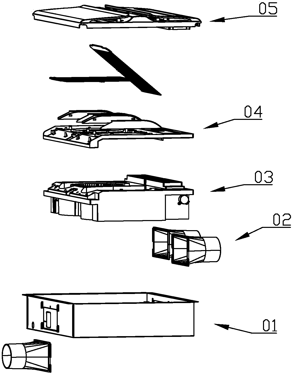
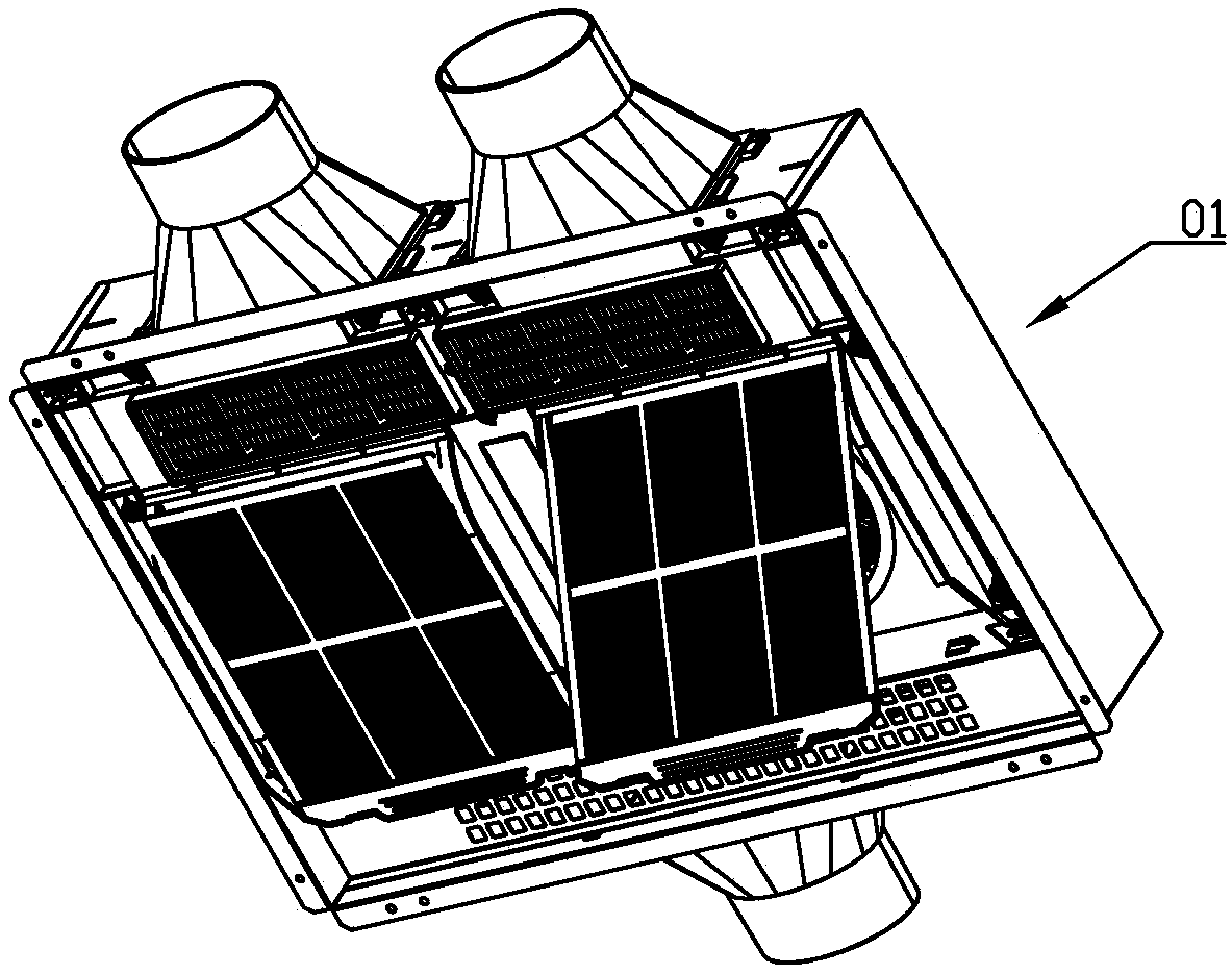
A technology of integrated ceiling and electrical appliances, which is applied in the field of new integrated ceiling electrical appliances, can solve the problems of low ventilation and heating efficiency, inability to realize ventilation and heating, and low ventilation efficiency of the wind wheel, so as to achieve good heating effect and air suction The effect is good, and the installation structure increases the reasonable effect

Pending Publication Date: 2018-12-21
浙江京盾科技有限公司
View PDF0 Cites 1 Cited by
  • Summary
  • Abstract
  • Description
  • Claims
  • Application Information

AI Technical Summary

Problems solved by technology

[0003] However, the existing integrated ceiling appliances all adopt the following structure to realize the above functions: 1. Only one motor, one wind wheel, and one PTC heater are designed, and the indoor ventilation and heating are realized through the positive and negative rotation of one motor. This structure can meet people's needs, but only one motor, one wind wheel is not efficient in ventilation, and it is impossible to realize ventilation and heating at the same time; second, design two motors, two wind wheels, and a PTC heater, One set of motors and wind wheels realizes ventilation, and the other set of motors, wind wheels and PTC heaters realizes heating. Although this structure can realize ventilation and heating at the same time, the efficiency of ventilation and heating is still not high, and the two If two motors work at full power at the same time, the noise will be loud and the service life will be reduced.

Method used


Image

  • Novel integrated ceiling electric appliance
  • Novel integrated ceiling electric appliance
  • Novel integrated ceiling electric appliance

Examples


Embodiment Construction

[0051] Below in conjunction with accompanying drawing, the present invention will be further described with specific embodiment;

[0052] In the description of the present invention, it should be understood that the orientations or positional relationships indicated by the terms "upper", "lower", "top", "bottom", "inner" and "outer" are based on those shown in the accompanying drawings. Orientation or positional relationship, or the orientation or positional relationship that is usually placed when the product of the invention is used, or the orientation or positional relationship that is commonly understood by those skilled in the art, is only for the convenience of describing the present invention and simplifying the description, rather than indicating or It should not be construed as limiting the invention by implying that a referenced device or element must have a particular orientation, be constructed, and operate in a particular orientation.

[0053] In addition, the ter...


PUM


Abstract

The invention discloses a novel integrated ceiling electric appliance. The novel integrated ceiling electric appliance comprises two integrated assemblies, and the integrated assemblies both can achieve ventilation and heating. The novel integrated ceiling electric appliance is characterized in that a volute air duct is hollow and separated to form a first chamber and a second chamber, a first airoutlet is formed in the first chamber, and a second air outlet is formed in the second chamber; the first integrated assembly is arranged in the first chamber, the second integrated assembly is arranged in the second chamber, the first integrated assembly is used for heating or replacing indoor air, and the second integrated assembly is used for heating or replacing indoor air; the volute air duct is provided with a cover plate, a first air inlet and a second air inlet are formed in the cover plate; the first air inlet is opposite to the first chamber, the first air inlet is covered with a first filter screen, the second air inlet is opposite to the second chamber, and the second air inlet is covered with a second filter screen; an iron box is further included; the volute air duct is entirely arranged in the iron box, and a first air inlet passage is formed in one side of the inner wall of the iron box.

Description

technical field [0001] The invention belongs to the technical field of electric appliances, and in particular relates to a novel integrated ceiling electric appliance. Background technique [0002] With the progress of society, people's requirements for quality of life are getting higher and higher. Indoor ventilation, heating, and lighting have become people's necessary conditions. Integrated ceiling appliances have emerged as the times require. In a broad sense, integrated ceiling appliances include lighting appliances, ventilation fans, There are three major modules of the heater, that is, the lamp for lighting, the ventilation fan for ventilation, and the Yuba (including lamp heater and wind heater) for heating. [0003] However, the existing integrated ceiling appliances all adopt the following structure to realize the above functions: 1. Only one motor, one wind wheel, and one PTC heater are designed, and the indoor ventilation and heating are realized through the posi...

Claims


Application Information

Patent Timeline
Patent Type & Authority Applications(China)
IPC IPC(8): E04B9/00E04B9/02F24F7/007F24F13/28
CPCF24F7/007F24F13/28E04B9/00E04B9/02F24F2221/34
Inventor 刘祥
Owner 浙江京盾科技有限公司
Learn More