A pre-combustion type aero-engine plasma igniter

An aero-engine and plasma technology, applied in the direction of machines/engines, gas turbine devices, mechanical equipment, etc., can solve the fuel channel insulation problem of the igniter, the fuel channel insulation problem, and the igniter Shorter service life and other problems, to achieve the effect of benefiting protection, improving safety and reliability, and increasing jet rigidity

Active Publication Date: 2019-08-02
AIR FORCE UNIV PLA
View PDF6 Cites 0 Cited by
  • Summary
  • Abstract
  • Description
  • Claims
  • Application Information

AI Technical Summary

Problems solved by technology

[0007] In the Chinese invention patent with the patent number of 201410568885, an elongated arc plasma jet igniter is disclosed, but there are several serious problems in the invention patent: (1) When the igniter is ignited, the arc is concentrated on the cathode Somewhere at the tip, due to the extremely high arc temperature, it is easy to ablate the cathode; (2) The igniter does not solve the insulation problem of the fuel channel well, and the fuel versatility is poor
[0008] Disclosed a kind of pre-chamber plasma jet igniter in existing research, but it has following several more serious problems: (1) this pre-chamber plasma jet igniter reacts near the anode, adopts anode The side-entry fuel method, this type of igniter greatly increases the temperature near the electrode, which easily damages the electrode and shortens the service life of the igniter, which is not conducive to practical applications and increases the probability of safety problems; (2) The structure of the igniter is relatively complicated, and the fuel inlet is located at the front end, which is not convenient for inserting into various chambers, and is not convenient for the application in the actual process; (3) The front end of the tungsten needle of the igniter is relatively sharp, and the arc is concentrated on a certain place at the tip of the cathode during ignition , because the arc temperature is extremely high, it is easy to ablate the cathode; (4) The igniter does not solve the insulation problem of the fuel channel well, and the fuel versatility is poor

Method used


Image

  • A pre-combustion type aero-engine plasma igniter
  • A pre-combustion type aero-engine plasma igniter
  • A pre-combustion type aero-engine plasma igniter

Examples


Embodiment Construction

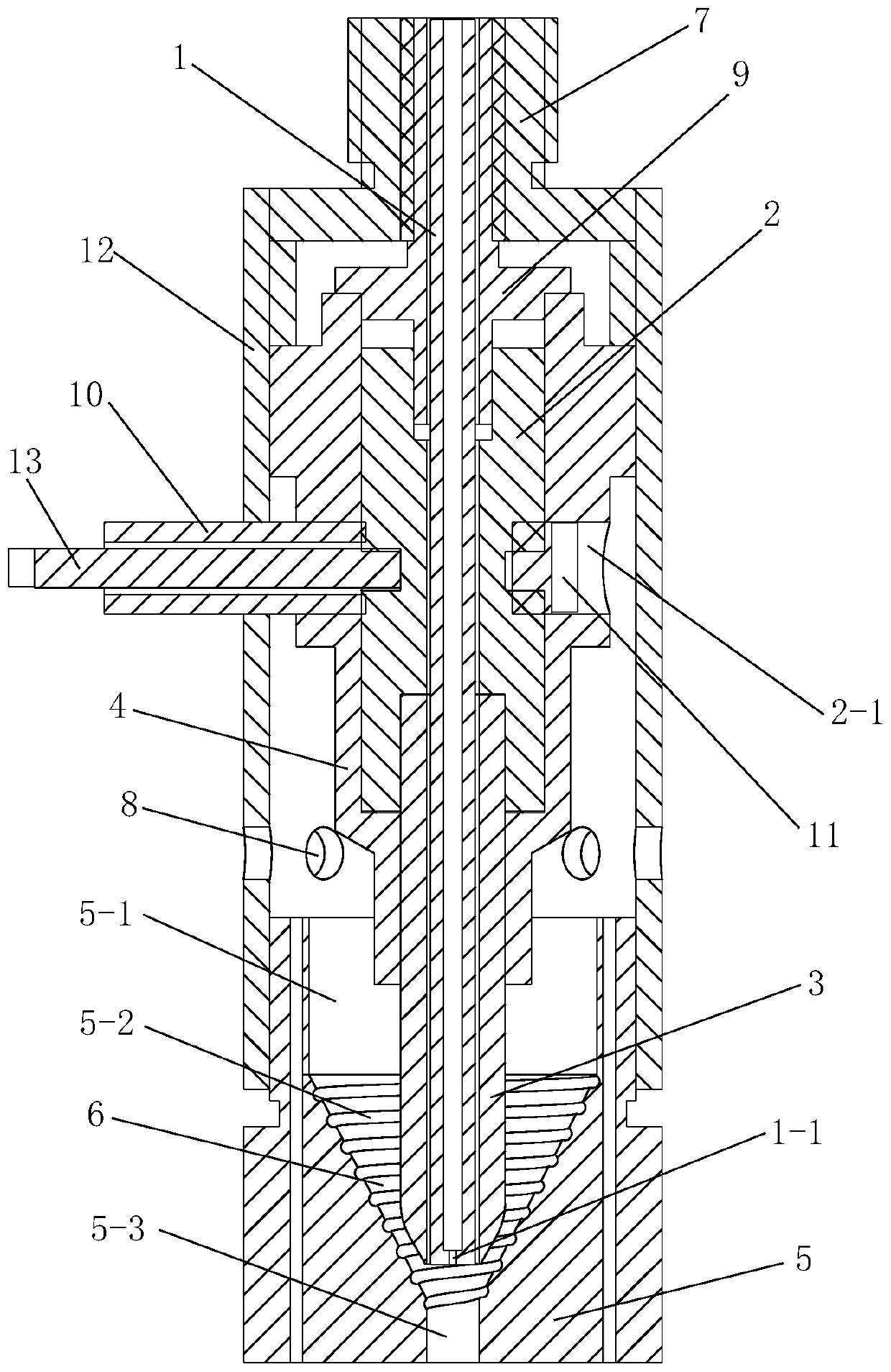
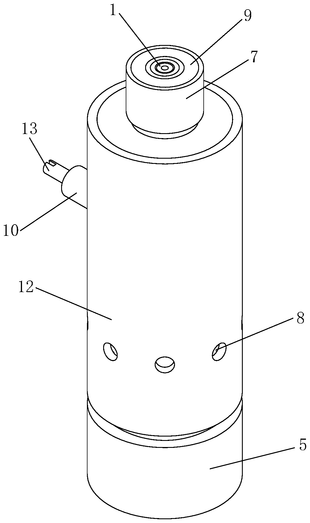
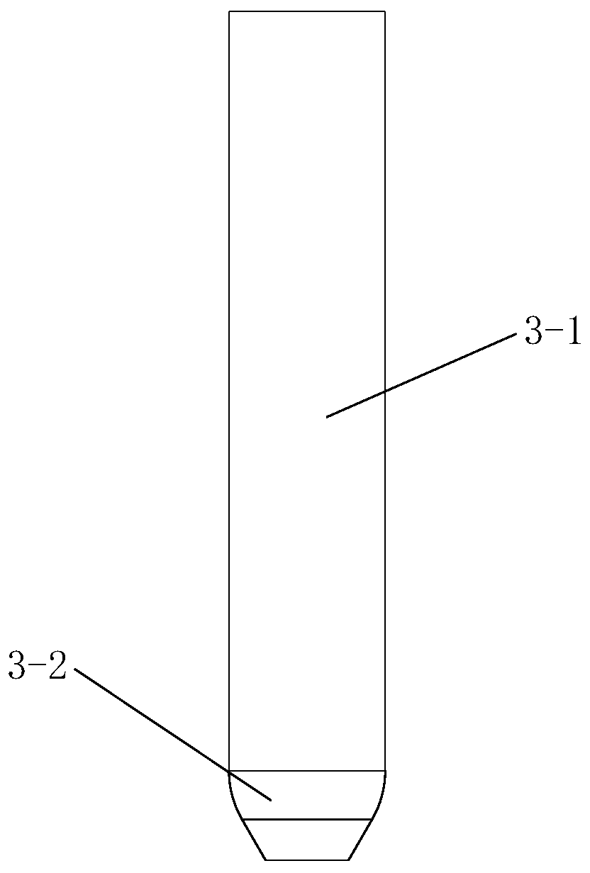
[0047] like figure 1 and figure 2 As shown, the present invention includes an outer tube 12, a ceramic tube fuel channel 1, a cathode part, an anode 5, an insulating sleeve 4, a bushing 9 and a top cover 7, and the cathode part is set in the middle and lower part of the ceramic tube fuel channel 1, so that The front end of the ceramic tube fuel channel 1 is provided with a nozzle 1-1, the insulating sleeve 4 is set on the middle and upper part of the cathode part, the insulating sleeve 4 is arranged in the outer tube 12, and the lower outer wall of the outer tube 12 A plurality of air inlets 8 are evenly opened in a week, the anode 5 is arranged below the air inlet 8, the upper part of the anode 5 is located in the outer tube 12 and is threadedly connected with the outer tube 12, and the anode 5 is hollow and rotates body; the cathode part includes a cathode holder 2 and a cathode 3, the lower part of the cathode holder 2 is provided with a groove with a first internal threa...


PUM


Abstract

The invention discloses a pre-combusted aircraft engine plasma igniter. The pre-combusted aircraft engine plasma igniter comprises an outer tube, a ceramic tube fuel channel, a cathode portion, an anode, an insulation sleeve, a bushing and a top cover; the cathode portion is installed on the middle-lower portion of the ceramic tube fuel channel in a sleeving mode, and a nozzle is arranged at the front end of the ceramic tube fuel channel; the insulation sleeve is installed on the middle-upper portion of the cathode portion in a sleeving mode and arranged in the outer tube; air inlet holes areformed in the outer wall of the lower portion of the outer tube, the anode is arranged under the air inlet holes, the upper portion of the anode is located in the outer tube and is in threaded connection with the outer tube, and the anode is a hollow revolving body; the cathode portion comprises a cathode base and a cathode, the upper portion of the cathode is in threaded connection with the lowerportion of the cathode base, and a spiral groove is formed in the middle of the inner wall of the anode; the lower end of the bushing is fixedly connected with the upper end of the cathode base; andthe top cover is installed outside the bushing in a sleeving mode, and the lower portion of the top cover is fixedly connected with the upper end of the outer tube. According to the pre-combusted aircraft engine plasma igniter, the ceramic tube fuel channel is additionally installed in the cathode portion, a reaction occurs outside the anode, therefore, electrodes are protected, the safety is improved, and the insulating problem is well solved.

Description

technical field [0001] The invention belongs to the technical field of aero-engines, in particular to a pre-combustion type aero-engine plasma igniter. Background technique [0002] The combustion chamber is a core component of an aero-engine, where continuous, high-velocity airflow burns. Combustion flames are easily blown out in such high-velocity airflows, so reliable ignition of the combustion chamber is critical during engine start-up. The success rate of ignition is directly related to the safe and reliable operation of the entire power plant, which puts forward higher requirements on the performance of the ignition device. At present, the ignition method used in the ignition device of the main combustion chamber of the aero turbine engine is electric nozzle ignition; the ignition method used in the ignition device of the afterburner mainly includes electric nozzle ignition, pre-chamber ignition, thermal jet ignition and catalytic ignition There are certain limitatio...

Claims


Application Information

Patent Timeline
Patent Type & Authority Patents(China)
IPC IPC(8): F02C7/266
CPCF02C7/266
Inventor 于锦禄蒋永健杨鹏王思博黄丹青蒋陆昀丁未何立明
Owner AIR FORCE UNIV PLA
Why Eureka
Try Eureka