
Engine, air inlet system of engine and electronic air spray valve used by system

A technology of air intake system and jet valve, which is applied to combustion engines, engine components, machines/engines, etc. It can solve problems such as complex structure, power loss, and difficulty in control, and achieve the effect of simplifying the intake structure and avoiding power loss

Inactive Publication Date: 2012-07-11
NINGBO YINZHOU DLT TECH CO LTD
View PDF6 Cites 0 Cited by
  • Summary
  • Abstract
  • Description
  • Claims
  • Application Information

AI Technical Summary

Problems solved by technology

[0003] At present, the air intake of the engine adopts a valve-type structure, which requires a complete set of parts such as camshafts and valve assemblies. During operation, the crankshaft drives the camshaft, and the camshaft controls the opening and closing of the valves. The amount of intake air is controlled by the cam line of the camshaft, and the drive connection is complicated; the entire intake process requires at least two power conversions, and a large amount of power is lost during the power conversion process; and this intake structure requires The air intake is designed on the cover, and the air intake manifold is separate, the structure is extremely complex and difficult to control

Method used


Image

  • Engine, air inlet system of engine and electronic air spray valve used by system
  • Engine, air inlet system of engine and electronic air spray valve used by system
  • Engine, air inlet system of engine and electronic air spray valve used by system

Examples


Embodiment Construction

[0036] The core of the present invention is to provide an electronic jet valve, which has a simple structure and can effectively control the amount of engine air intake under the condition of small power loss.

[0037] In order to enable those skilled in the art to better understand the technical solutions of the present invention, the present invention will be further described in detail below with reference to the accompanying drawings and specific embodiments.

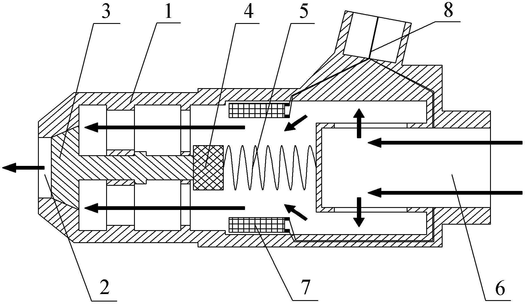
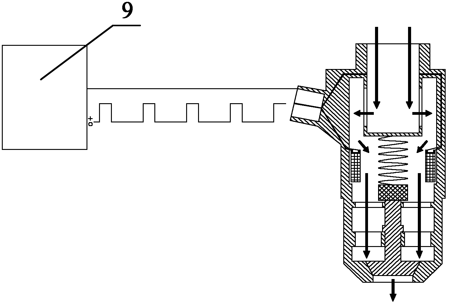
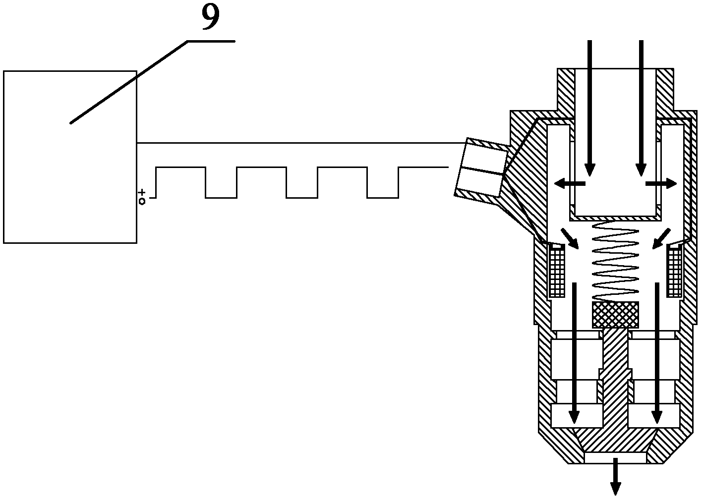
[0038] Please refer to figure 1 , figure 2 with image 3 , figure 1 It is a schematic diagram of the structure of the electronic jet valve provided by the present invention; figure 2 The schematic diagram of the short pulse of the electronic control unit to control the electronic jet valve; image 3 The schematic diagram of the long pulse of the electronic control unit to control the electronic jet valve.

[0039] Such as figure 1 As shown, the electronic jet valve provided by the present invention includes a valve body 1...


PUM


Abstract

The invention discloses an electronic air spray valve. When a current signal is transmitted by an electronic control unit, an electromagnetic coil is energized, electromagnetic force is generated, work is done by overcoming the elastic force of an elastic restoring piece, an armature and a valve head are picked up, the electronic air spray valve is opened at the moment and high-pressure air enters a valve body from a high-pressure air inlet at the tail of the valve body, is sprayed out through a high-pressure air outlet and enters an air cylinder; and when the current signal transmitted by the electronic control unit is cut off, the electromagnetic coil is de-energized, the electromagnetic force is released, the armature and the valve head are restored under the effect of the elastic force of the elastic restoring piece, the electronic air spray valve is closed, a complete air inlet process is completed and the air inlet amount can be controlled through the length of electronic pulses. Therefore, the electronic air spray valve has the advantages that the parts such as an air valve assembly are omitted, the air inlet structure is simplified, the power loss caused by complex connection is avoided and the air inlet amount can be effectively controlled. The invention additionally discloses an engine and an air inlet system of the engine, wherein the air inlet system uses the electronic air spray valve.

Description

Technical field [0001] The present invention relates to the field of engine technology, in particular to an engine and its air intake system and an electronic jet valve contained in the system. Background technique [0002] The engine mixes liquid or gas fuel with air and directly inputs it into the high-pressure combustion chamber inside the cylinder to burn and explode to generate power. It is also a heat engine that converts heat energy into mechanical energy. [0003] At present, the intake of the engine adopts a valve type structure. The use of this structure requires a complete set of components such as camshafts and valve components. The crankshaft drives the camshaft during operation, and the camshaft controls the opening and closing of the valve. The intake air volume is controlled by the cam profile of the camshaft, and the drive connection is complicated; the entire intake process needs to go through at least two power conversions. These, a lot of power is lost in the po...

Claims


Application Information

Patent Timeline
Patent Type & Authority Applications(China)
IPC IPC(8): F01L9/04F02B37/00F01L9/20
CPCY02T10/144Y02T10/12
Inventor 徐敏武
Owner NINGBO YINZHOU DLT TECH CO LTD
Learn More