[0015] The technical solutions in the embodiments of the present invention will be clearly and completely described below in conjunction with the accompanying drawings in the embodiments of the present invention. Obviously, the described embodiments are only a part of the embodiments of the present invention, rather than all the embodiments. Based on the embodiments of the present invention, all other embodiments obtained by those of ordinary skill in the art without creative work shall fall within the protection scope of the present invention.
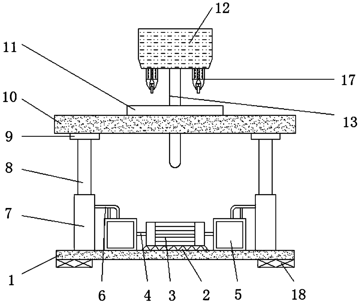
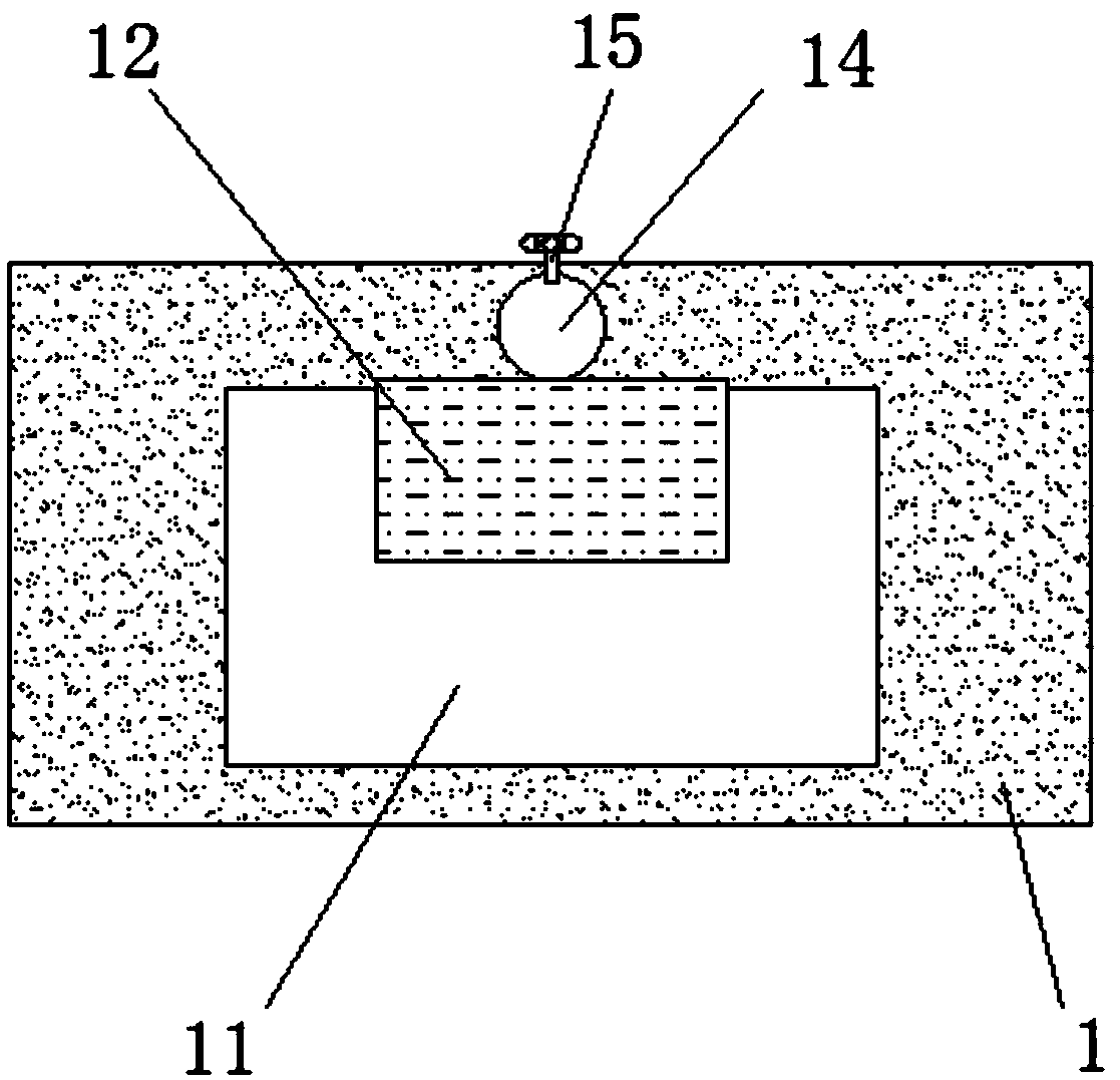
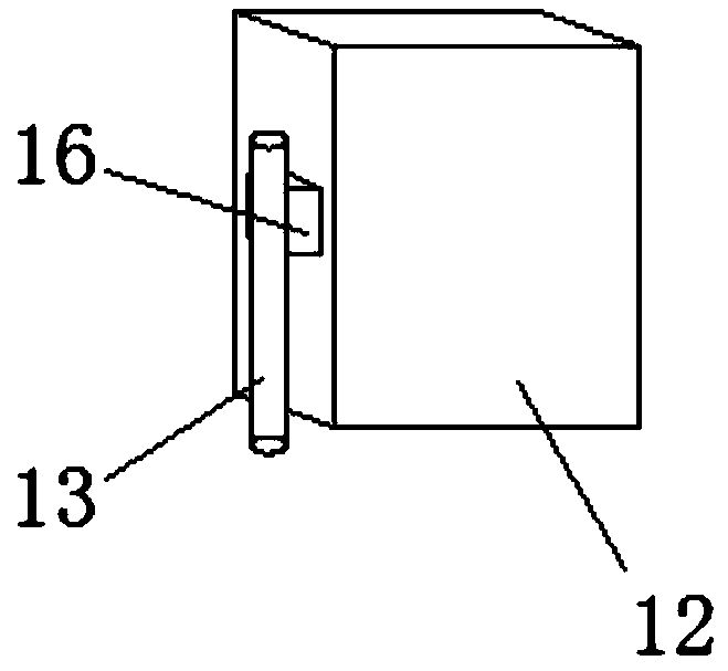
[0016] See Figure 1-3 , The present invention provides a technical solution: a marking device with height adjustment function, including a device base 1, a motor base 2, a motor 3, a connecting shaft 4, a pneumatic pump 5, an air pipe 6, a column 7, and a pneumatic telescopic rod 8. , Sleeve 9, operating table 10, storage plate 11, limit plate 12, connecting rod 13, connecting rod groove 14, adjusting bolt 15, connecting block 16, marking device 17 and anti-skid block 18, in the upper part of the device base 1. A motor base 2 is provided at the end, and a motor 3 is installed above the motor base 2, and a connecting shaft 4 is arranged on the outside of the motor 3. The motor base 2 and the motor 3 constitute a disassembly and installation structure, and the left and right sides of the motor 3 are connected with The air pump 5 is disassembled and installed to facilitate regular inspection and maintenance of the motor 3. The air pump 5 is installed on the left side of the connecting shaft 4, and the air pump 5 is installed above the base 1 of the device, and the air pump 5 is connected to the top The trachea 6, the upper left and right ends of the device base 1 are equipped with uprights 7, and above the uprights 7 are installed pneumatic telescopic rods 8, while the uprights 7 and the air pipe 6 are connected to each other, and the uprights 7 are arranged symmetrically with respect to the axis of the device base 1. The inside of the column 7 is connected with a pneumatic telescopic rod 8, and two columns 7 are provided to ensure the stable performance of the device. A sleeve 9 is installed on the top of the pneumatic telescopic rod 8, and an operating table is arranged above the sleeve 9 10. A storage plate 11 is fixed above the operating table 10, and a connecting rod groove 14 is provided on the outside of the holding plate 11, and an adjusting bolt 15 is provided on the outside of the connecting rod groove 14, and the operating table 10 and the device base 1 mutually It is installed in parallel, and the width of the operating table 10 is equal to the width of the device base 1. The parallel setting ensures the stable performance of the device during marking. The storage plate 11 is made of stainless steel and is symmetrical about the center of the operating table 10. The stainless steel material is relatively strong and difficult Wear, the connecting rod 13 penetrates and connects to the inside of the connecting rod groove 14, and the upper end of the connecting rod 13 is connected to the limit plate 12, a connecting block 16 is installed between the limit plate 12 and the connecting rod 13, and the limit plate 12 An engraving device 17 is provided at the lower end. The engraving device 17 and the storage plate 11 are arranged perpendicular to each other, and the engraving device 17 forms a disassembly and installation structure with respect to the limit plate 12, and the vertical arrangement avoids the deviation of the engraving due to the tilt of the device during engraving. To facilitate regular maintenance and replacement of the marking device 17, the anti-skid block 18 is arranged on the lower side of the device base 1.
[0017] Working principle: First place the engraved item above the storage plate 11, and then use the pneumatic pump 5 to drive the pneumatic telescopic rod 8 up and down to adjust the operating table 10 to a suitable height. Because the limit plate 12 is set above the connecting rod 13, In addition, the connecting rod 13 is connected through the inside of the connecting rod groove 14 and the adjusting bolt 15 is provided on the outside of the connecting rod groove 14. Therefore, the connecting rod 13 can be adjusted by the adjusting bolt 15 to adjust the height of the limit plate 12. Since two marking devices 17 are provided at the lower end of the limit plate 12, two items can be marked at the same time, which increases the work efficiency of marking. The bottom and left ends of the device base 1 are provided with anti-skid blocks 18, which are used for marking. At the same time, it prevents the device from shaking left and right due to marking, and increases the stability of the device. This is the working principle of the marking device with a height adjustment function.
[0018] Finally, it should be noted that the above content is only used to illustrate the technical solutions of the present invention, rather than to limit the scope of protection of the present invention. Simple modifications or equivalent substitutions made by those skilled in the art to the technical solutions of the present invention do not depart from the present invention. The essence and scope of the technical solution of the invention.