
A high-efficiency oil-water separation device

An oil-water separation device, oil-water separation technology, applied in the direction of separation method, liquid separation, grease/oily substance/floating matter removal device, etc., can solve the problems of blockage of oil discharge pipe, oil accumulation in discharge pipe, inconvenient cleaning, etc., and achieve the goal of using Convenience, avoid clogging effect

Active Publication Date: 2021-07-13
南京瑞升机械制造有限公司
View PDF6 Cites 2 Cited by
  • Summary
  • Abstract
  • Description
  • Claims
  • Application Information

AI Technical Summary

Problems solved by technology

[0004] However, in actual use, when the grease is discharged through the discharge pipe, due to the viscosity of the grease, it will adhere to the inner wall of the discharge pipe. After a long period of use, the discharge pipe will accumulate oil, which will eventually lead to the blockage of the oil discharge pipe. Very inconvenient to clean

Method used


Image

  • A high-efficiency oil-water separation device
  • A high-efficiency oil-water separation device
  • A high-efficiency oil-water separation device

Examples


Embodiment Construction

[0038] The following is attached Figure 1-6 The present invention is described in further detail.

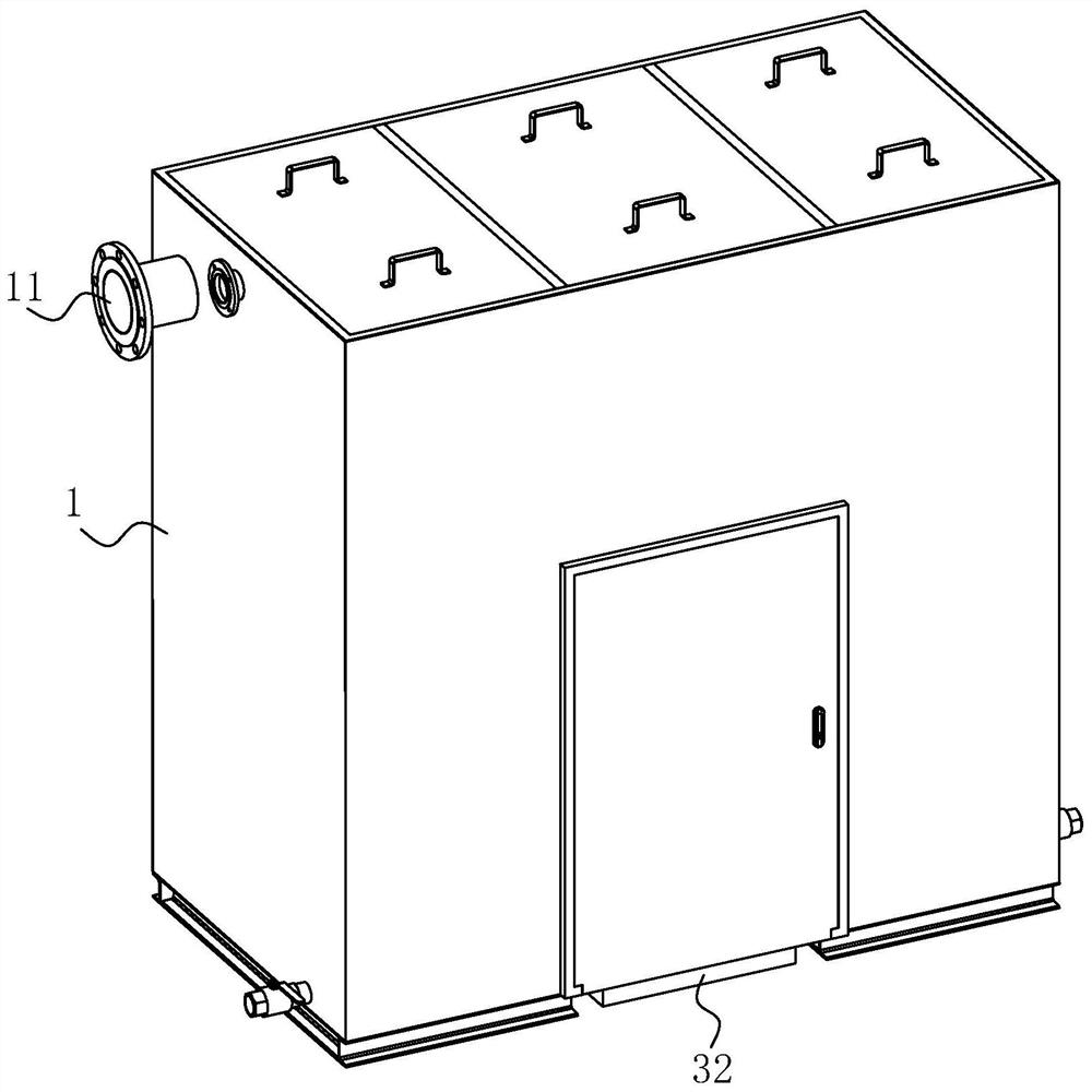
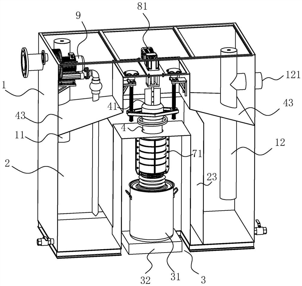
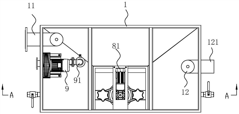
[0039] refer to figure 1 as well as figure 2 , is a high-efficiency oil-water separation device disclosed in the present invention, including a box body 1 and an oil-water separation bin 2 arranged in the box body 1, and a water inlet pipe 11 communicating with the oil-water separation bin 2 is provided on the box body 1, and kitchen sewage passes through The water inlet pipe 11 enters the oil-water separation chamber 2, and the bottom of the water inlet pipe 11 is close to the bottom of the oil-water separation chamber 2 of the casing 1. A collection chamber 3 is also provided in the box body 1, and the collection chamber 3 is embedded in the oil-water separation chamber 2, that is, the oil-water separation chamber 2 wraps the collection chamber 3. Refer to Figure 6 , an oil discharge pipe 4 is arranged between the oil-water separation chamber 2 and the collection chamber...


PUM


Abstract

The invention relates to a high-efficiency oil-water separation device, which includes a box body and an oil-water separation bin arranged in the box body, a water inlet pipe communicating with the oil-water separation bin is arranged on the box body, and a water inlet pipe embedded in the oil-water separation bin is arranged in the box body The collection chamber, the oil-water separation chamber and the collection chamber are connected by a vertical oil discharge pipe, and the tops of the oil discharge pipes gather to form an oil discharge port with a cross-sectional area smaller than that of the oil discharge pipe, and an oil guide ring is connected to the inner wall of the oil discharge port. At this time, when the liquid level in the oil-water separation chamber is higher than the oil discharge port, the oil floating on the top of the liquid surface enters the oil discharge port, along the oil guide ring, falls out of the oil discharge pipe, and the oil that falls into the collection chamber Just collect them. Because the oil only drips along the oil guide ring, the inner diameter of the oil guide ring is smaller than the inner diameter of the oil discharge pipe, so that the oil will not contact the inner wall of the oil discharge pipe, which can effectively avoid the phenomenon of hanging oil on the inner wall of the oil discharge pipe.

Description

technical field [0001] The invention relates to the technical field of oil-water separation, in particular to a high-efficiency oil-water separation device. Background technique [0002] In Chinese society, the oily sewage produced by kitchens, restaurants, meat processing plants, slaughterhouses, residential areas and other industries is generally only treated by outdated sedimentation technologies such as grease traps and simple oil-water separation devices, and cannot be used. The oil, water and impurities in the sewage are fully separated, and the discharged sewage contains a lot of oil, which causes the blockage of the urban underground pipe network and the pollution of the river. [0003] The invention patent with the notification number CN104086008B provides a fully automatic integrated kitchen oil-water separator. When in use, the sewage is introduced into the secondary separator through the separation guide pipe, and the sewage is separated for the second time under...

Claims


Application Information

Patent Timeline
Patent Type & Authority Patents(China)
IPC IPC(8): C02F1/40
CPCC02F1/40
Inventor 唐占权
Owner 南京瑞升机械制造有限公司
Learn More