System and method for current value detection and mobile terminal
A detection system and current value technology, applied in electric vehicles, measuring current/voltage, current collectors, etc., can solve problems such as low accuracy of current value
- Summary
- Abstract
- Description
- Claims
- Application Information
AI Technical Summary
Problems solved by technology
Method used
Image

Examples
Embodiment 1
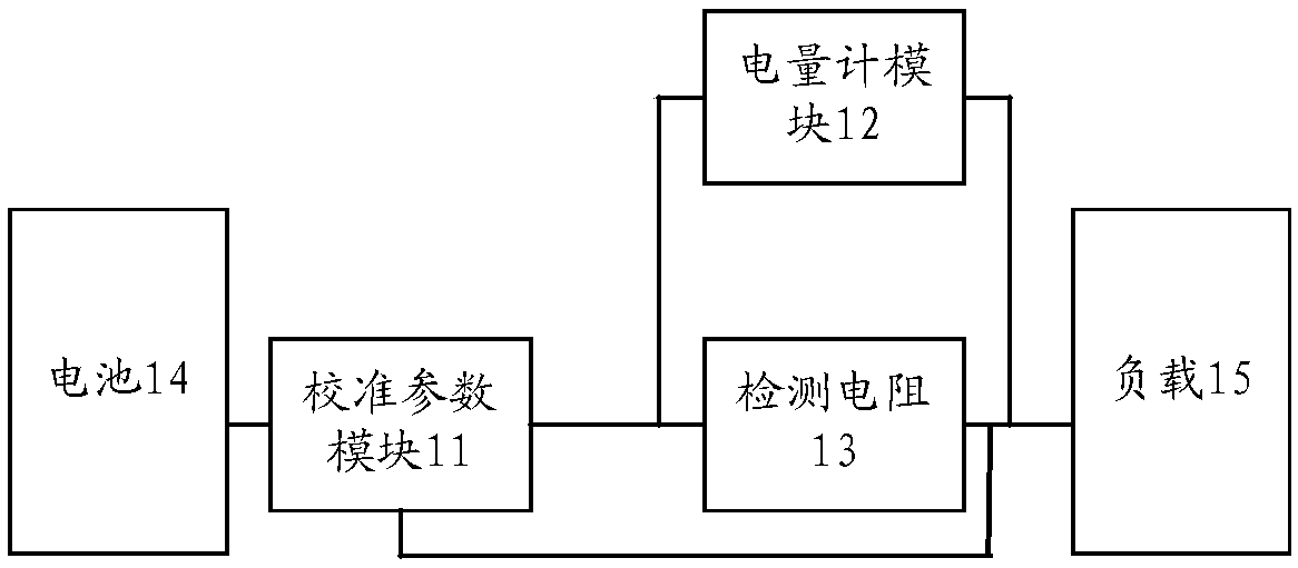
[0031] figure 1 It is a schematic diagram of a current value detection system provided by Embodiment 1 of the present invention, such as figure 1 As shown, the system can include:
[0032] Calibration parameter module 11 , fuel gauge module 12 and detection resistor 13 .
[0033] Wherein, the fuel gauge module 12 can be connected in parallel with the detection resistor 13, that is, the fuel gauge module 12 is electrically connected to both ends of the detection resistor 13 respectively, and the first end of the calibration parameter module 11 can be electrically connected to one end of the battery 14, The second end of the calibration parameter module 11 can be electrically connected to the first end of the detection resistor 13, the third end of the calibration parameter module 11 can be electrically connected to the second end of the detection resistor 13, and the second end of the detection resistor 13 It can be electrically connected with the load 15 .
[0034] Further,...
Embodiment 2
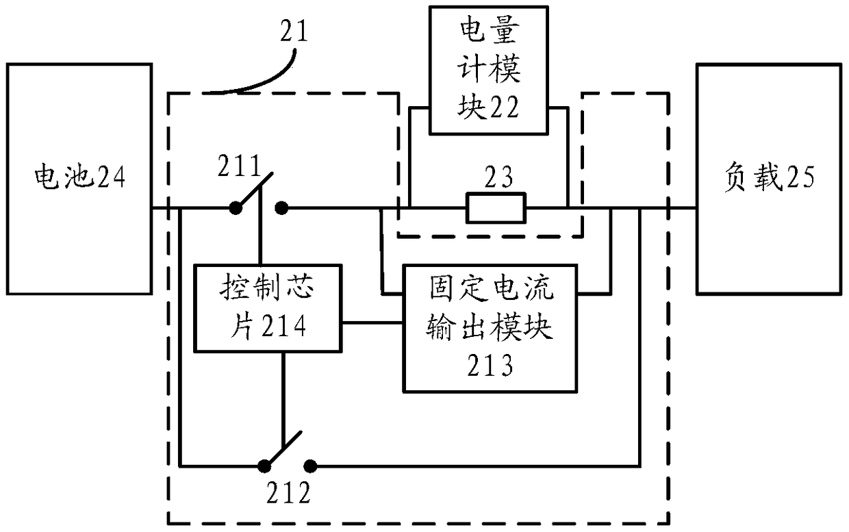
[0042] figure 2 It is a schematic diagram of a current value detection system provided by Embodiment 2 of the present invention, such as figure 2 As shown, the system can include:
[0043] Calibration parameter module 21 , fuel gauge module 22 and detection resistor 23 .
[0044] Wherein, the fuel gauge module 22 can be connected in parallel with the detection resistor 23, the first end of the calibration parameter module 21 can be electrically connected to one end of the battery 24, and the second end of the calibration parameter module 21 can be electrically connected to the first end of the detection resistor 23. The third end of the calibration parameter module 21 can be electrically connected to the second end of the detection resistor 23, and the second end of the detection resistor 23 can be electrically connected to the load 25.
[0045] Specifically, the calibration parameter module 21 may include a first switch 211 , a second switch 212 , a fixed current output m...
Embodiment 3
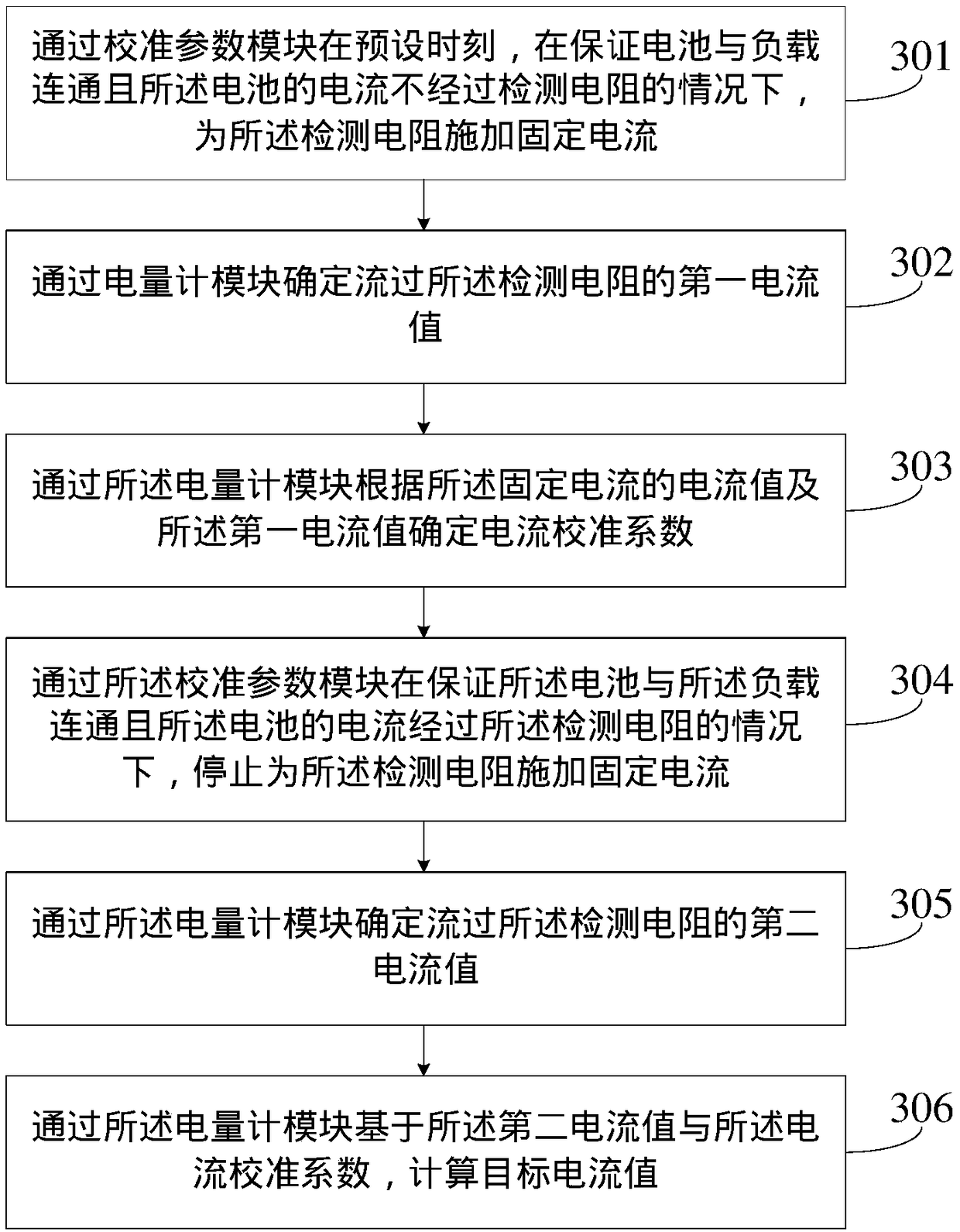
[0055] image 3 It is a flow chart of the steps of a current value detection method provided in Embodiment 3 of the present invention, and the method can be applied to figure 1 provided by the current value detection system, such as image 3 As shown, the method may include:
[0056] Step 301 , apply a fixed current to the detection resistor at a preset time through the calibration parameter module under the condition that the battery is connected to the load and the current of the battery does not pass through the detection resistor.
[0057] In the embodiment of the present invention, under the condition that the battery is connected to the load and the battery current does not pass through the detection resistor, the method of applying a fixed current to the detection resistor can ensure that only a fixed current flows through the detection resistor, thereby avoiding the subsequent steps. , to determine the accuracy of the first current value.
[0058] Step 302. Determin...
PUM
 Abstract
Description
Claims
Application Information
 - R&D Engineer
- R&D Manager
- IP Professional
- Industry Leading Data Capabilities
- Powerful AI technology
- Patent DNA Extraction
Browse by: Latest US Patents, China's latest patents, Technical Efficacy Thesaurus, Application Domain, Technology Topic.
© 2024 PatSnap. All rights reserved.Legal|Privacy policy|Modern Slavery Act Transparency Statement|Sitemap