Alignment Mark Recognition System

A mark and phase delay technology, which is applied in the field of alignment mark identification system, can solve problems such as difficulty in alignment and bonding

Active Publication Date: 2021-06-25
INTERFACE TECH CHENGDU CO LTD +2
View PDF4 Cites 0 Cited by
  • Summary
  • Abstract
  • Description
  • Claims
  • Application Information

AI Technical Summary

Problems solved by technology

[0004] The main purpose of the present invention is to provide an alignment mark identification system to solve the problem of difficulty in alignment and bonding due to the lack of space for alignment marks in the frame routing area of ​​narrow frame products

Method used


Image

  • Alignment Mark Recognition System
  • Alignment Mark Recognition System
  • Alignment Mark Recognition System

Examples


Embodiment Construction

[0032] The technical means and structures adopted in the present invention are illustrated in detail with reference to the embodiments of the present invention. The features and functions are as follows, but it should be noted that the content does not constitute a limitation of the present invention.

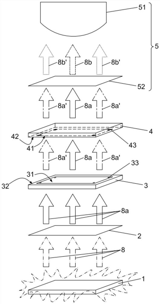
[0033] see figure 1 As shown, it is a schematic diagram of the system principle of an embodiment of the alignment mark recognition system of the present invention. The present invention provides an alignment mark recognition system, which is applied to the alignment and lamination of a touch panel and a display device, comprising: a light source 1, a first polarizer 2, a first transparent substrate 3, and a second transparent substrate 4 and a light receiver 5 .

[0034] The light source 1 is used to emit a light 8 , which is received by the light receiver 5 after passing through the first polarizer 2 , the first transparent substrate 3 , and the second transparent substrate 4...


PUM


Abstract

The invention provides an alignment mark recognition system, which uses the visible area of ​​the touch module to set a transparent alignment mark made of a phase delay material, and then passes through two polarizers so that the light receiver can effectively identify the alignment mark. The alignment procedure for graphics has improved the problem that there is no space to set the alignment mark in the border wiring area of ​​​​narrow bezel products.

Description

technical field [0001] The technology of the present invention relates to the field of touch control, in particular to an alignment mark recognition system that uses the visible area of ​​the substrate for alignment and lamination. Background technique [0002] Nowadays, the technological development of touch display devices is very diverse. According to different principles, they can be divided into resistive, capacitive, optical, electromagnetic induction, and sound wave induction. Due to the increasing requirements of electronic products on the effective use efficiency of the screen display area, touch display devices with narrow bezels or even ultra-narrow bezels are continuously launched under the demand of high screen-to-body ratio. [0003] In the conventional touch display device, the frame area is a space for designing wiring of various components and alignment marks. The space for tokens is getting smaller and smaller. Because the frame area needs to be used pref...

Claims


Application Information

Patent Timeline
Patent Type & Authority Patents(China)
IPC IPC(8): G06F3/042
CPCG06F3/0421G06F2203/04109
Inventor 赖世伦
Owner INTERFACE TECH CHENGDU CO LTD
Why Eureka
Try Eureka