A switch cabinet connection device and an installation method thereof

A connection device and switchgear technology, applied in switchgear, substation/switch layout details, substation/distribution device enclosure, etc., can solve the problem of increasing the development cost of connection device accessories, increasing the difficulty of design and installation of switchgear, and connecting device accessories. Problems such as large quantity, etc., to achieve the effect of improving the efficiency of connection and installation, reducing product inventory, and reducing assembly parts

Pending Publication Date: 2018-12-21
成都盛帮双核科技有限公司
View PDF5 Cites 4 Cited by
  • Summary
  • Abstract
  • Description
  • Claims
  • Application Information

AI Technical Summary

Problems solved by technology

[0002] When the existing switchgears are connected and installed with each other, especially when the switchgear products of different current levels or the switchgear products of the same current level are spliced ​​and assembled separately for the ring network cabinet and the GIS cabinet, different current levels and different voltages Different levels of switchgear products require more connection accessories, resulting in a large number of connection device accessories required, connection installation is more troublesome, and sometimes it is necessary to change the structural size of the switchgear, which not only increases the development of connection device accessories cost, but also correspondingly increases the difficulty of design and installation of the switchgear

Method used


Image

  • A switch cabinet connection device and an installation method thereof
  • A switch cabinet connection device and an installation method thereof
  • A switch cabinet connection device and an installation method thereof

Examples


Embodiment Construction

[0025] In order to make the object, technical solution and advantages of the present invention clearer, the present invention will be described in detail below in conjunction with the accompanying drawings and specific embodiments. It should be understood that the specific embodiments described here are only used to explain the present invention, not to limit the present invention.

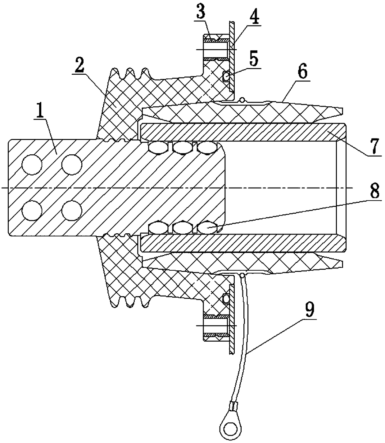
[0026] Such as figure 1 The switchgear connection device shown mainly includes a connecting conductor 1, an insulating sleeve 2, an insulating connecting sleeve 6, a central conductor 7, a spring 8 and a grounding wire 9. The central conductor 7 is a hollow cylindrical structure, one end of which is connected to the A socket structure is formed between one end of the connecting conductor 1 , and a spring 8 is arranged at the socketing position between the connecting conductor 1 and the central conductor 7 , and the insulating connecting sleeve 6 is installed between the insulating sleeve 2 and the...


PUM


Abstract

A switch cabinet connecting device and a mounting method are provided. A switch cabinet connecting device comprises a connecting conductor, an insulating sleeve, an insulated connection sleeve, a central conductors and a spring, one end of the connectiong conductor passes through the insulating sleeve, and a sealing and fixing connection structure is formed between the one end of the connectiong conductor and the insulating sleeve, The other end of the connecting conductor is exposed to the insulating sleeve, and the central conductor is of a hollow cylindrical structure, and a sleeve structure is formed between one end of the connecting conductor and one end of the connecting conductor. A spring is arranged at the sleeve part between the connecting conductor and the central conductor, andthe insulating connection sleeve is installed between the insulating sleeve and the central conductor. The invention is applicable to the connection assembly between switchgear cabinets of differentcurrent grades, and can reduce the stock of assembled parts and products regardless of switchgear cabinets or connecting device enterprises, and avoid connecting devices of different current grades adopting different molds, so as to easily realize the mass production of products, reduce the cost of product research and development, and also reduce the cost of products themselves.

Description

technical field [0001] The invention relates to the technical field of switch cabinet connection and installation, in particular to a switch cabinet connection device and installation method applied to voltages and current levels of 35kV, 2500A and below. Background technique [0002] When the existing switchgears are connected and installed with each other, especially when the switchgear products of different current levels or the switchgear products of the same current level are spliced ​​and assembled separately for the ring network cabinet and the GIS cabinet, different current levels and different voltages Different levels of switchgear products require more connection accessories, resulting in a large number of connection device accessories required, connection installation is more troublesome, and sometimes it is necessary to change the structural size of the switchgear, which not only increases the development of connection device accessories Cost, but also correspon...

Claims


Application Information

Patent Timeline
Patent Type & Authority Applications(China)
IPC IPC(8): H02B1/30H02B3/00H02B1/20H02G3/22
CPCH02B1/20H02B1/308H02B3/00H02G3/22
Inventor 张金梅王海鱼赖凯贺缝建杨萧
Owner 成都盛帮双核科技有限公司
Why Eureka
Try Eureka