Al technical title is built by PatSnap Al team. It summarizes the technical point description of the patent document.
A technology of busway and mounting plate, applied in the field of busway, which can solve the problems of inconvenient busway installation, unfavorable busway use, and reduced installation efficiency, so as to avoid the movement of copper bars, facilitate heat dissipation, and improve installation efficiency.
Inactive Publication Date: 2018-12-21
镇江宝源电仪设备有限公司
View PDF13 Cites 12 Cited by
Summary
Abstract
Description
Claims
Application Information
AI Technical Summary
This helps you quickly interpret patents by identifying the three key elements:
Problems solved by technology
Method used
Benefits of technology
Problems solved by technology
[0003] However, the existing bus ducts mostly use multiple profiles for clamping, which is relatively troublesome during assembly and maintenance, and the existing bus ducts mostly rely on the shell for heat dissipation, which has poor heat dissipation, which is not conducive to the use of bus ducts At the same time, most of the existing bus ducts do not contain height-adjustable installation mechanisms. When the installation of the bus duct encounters a mounting surface that is not at the same level, more gaskets need to be placed during installation, which reduces the efficiency of installation. Easy installation of bus duct
Method used
Image
Click on the blue label to locate the original text in one second.
Reading with bidirectional positioning of images and text.
Examples
Embodiment Construction
[0019] The following will clearly and completely describe the technical solutions in the embodiments of the present invention with reference to the accompanying drawings in the embodiments of the present invention. Obviously, the described embodiments are only some, not all, embodiments of the present invention. Based on the embodiments of the present invention, all other embodiments obtained by persons of ordinary skill in the art without making creative efforts belong to the protection scope of the present invention.
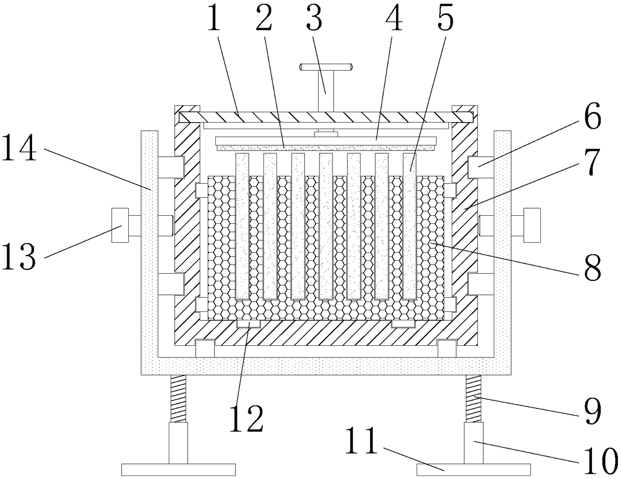
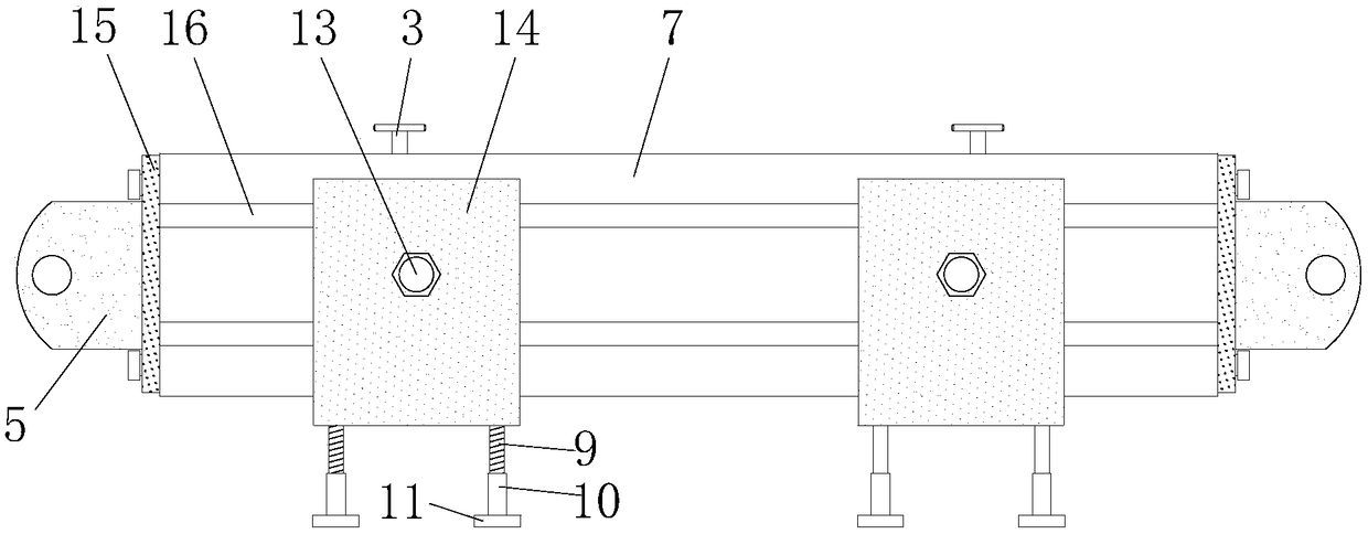
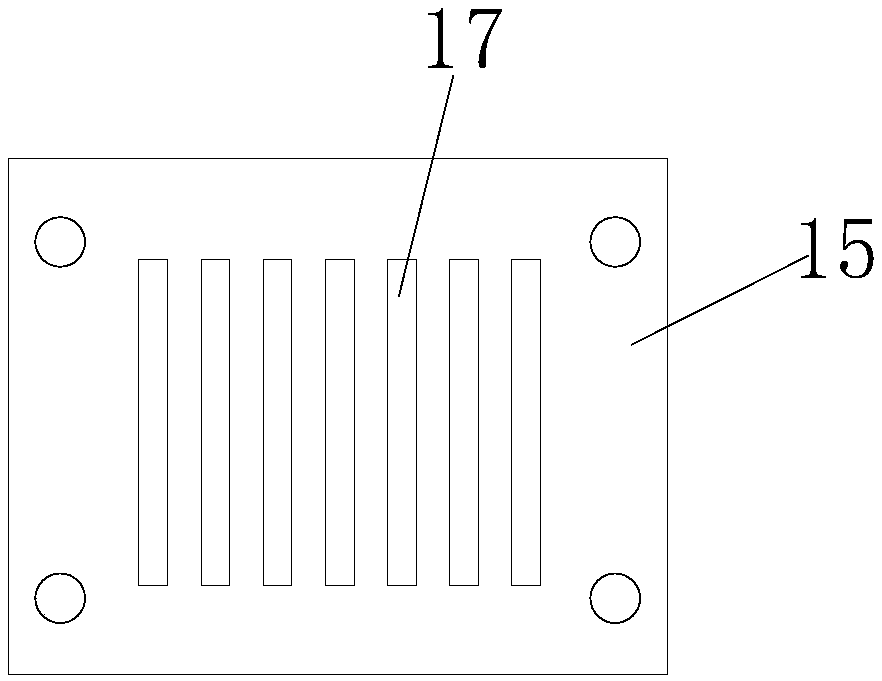
[0020] see Figure 1-3 As shown, an easy-to-install bus duct includes a U-shaped housing 7, a copper bar holder 8, a top plate 1, a copper bar 5, an end cover 15, a pressure plate 4, a silicone sheet 2, a pressure plate adjustment bolt 3 and an installation mechanism. The U-shaped shell 7 has card slots on the inner walls of both sides corresponding to each other and the top surface of the bottom, which is convenient for the installation of the copper row hold...
PUM
Abstract
The invention discloses a bus slot for easy installation, which comprises a top plate, a silica gel sheet, a pressure plate adjusting bolt, a pressure plate, a copper bar, a slide block, a U-shaped shell, a copper bar clamp seat, a threaded column, a threaded cylinder, a mounting bottom plate, a clamp block, a fastening bolt, a U-shaped mounting plate end cover, a sliding slot and a copper bar socket. A silica gel sheet is attached to the bottom of the pressing plate of the invention, the silica gel sheet can not only fix the copper bar well to avoid the movement of the copper bar, and it canalso take away part of the heat generated by the bus slot when it is working, conducive to the heat dissipation of the bus slot, at the same time, the copper bar card socket is installed in the U-shaped shell in a clamping manner, The bus slot reduces the use of screws and facilitates the assembly of the busbar groove. When the mounting surface is not on the same horizontal plane, the rotatable screw barrel changes the distance between the mounting bottom plate and the U-shaped shell, and finally the busbar groove is kept horizontal after installation, no gasket is needed, the mounting efficiency of the busbar groove is improved, and the installation of the busbar groove is beneficial to the busbar groove.
Description
technical field [0001] The invention relates to a bus duct, in particular to a bus duct that is easy to install, and belongs to the technical field of bus duct applications. Background technique [0002] Busway is a closed metal device composed of copper and aluminum busbar columns, which is used to distribute large power to various components of the decentralized system. With the emergence of modern engineering facilities and equipment, the power consumption of all walks of life is increasing rapidly. , the traditional cable used as a transmission wire can no longer meet the requirements in the large current transmission system. The parallel use of multiple cables has brought a lot of inconvenience to the on-site installation and construction connection. Compared with traditional cables, it fully demonstrates its superiority in high-current transmission, and has increasingly replaced wires and cables in indoor low-voltage power transmission trunk line projects. [0003] Ho...
Claims
Application Information
Patent Timeline
Application Date:The date an application was filed.
Publication Date:The date a patent or application was officially published.
First Publication Date:The earliest publication date of a patent with the same application number.
Issue Date:Publication date of the patent grant document.
PCT Entry Date:The Entry date of PCT National Phase.
Estimated Expiry Date:The statutory expiry date of a patent right according to the Patent Law, and it is the longest term of protection that the patent right can achieve without the termination of the patent right due to other reasons(Term extension factor has been taken into account ).
Invalid Date:Actual expiry date is based on effective date or publication date of legal transaction data of invalid patent.