Vibration damping rotor iron core, vibration damping rotor and electric machine

A technology of rotor iron core and iron core, applied in the direction of electrical components, electromechanical devices, magnetic circuit rotating parts, etc., can solve the problems of motor vibration reduction performance, vibration reduction material falling off, motor quality abnormality, etc., to achieve enhanced reliability , Strengthen the tangential force and ensure the reliability of the rotor

Active Publication Date: 2018-12-21
GREE ELECTRIC APPLIANCES INC +1
View PDF7 Cites 2 Cited by
  • Summary
  • Abstract
  • Description
  • Claims
  • Application Information

AI Technical Summary

Problems solved by technology

[0005] Therefore, the technical problem to be solved by the present invention is to overcome the defect that the damping material between the inner and outer rotors of the motor rotor in the prior art tends to fall off in the circumferential direction, which leads to a decrease in the vibration damping performance of the motor and abnormal motor quality. Thereby providing a vibration-damping rotor core, a vibration-damping rotor and a motor

Method used


Image

  • Vibration damping rotor iron core, vibration damping rotor and electric machine
  • Vibration damping rotor iron core, vibration damping rotor and electric machine
  • Vibration damping rotor iron core, vibration damping rotor and electric machine

Examples


Embodiment Construction

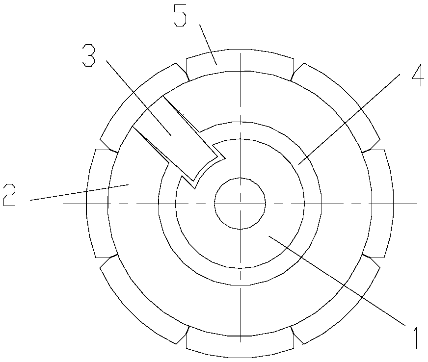
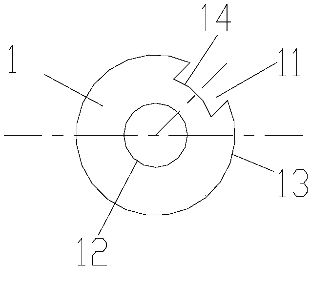
[0045] like Figure 1-8 As shown, the present invention provides a vibration-damping rotor core, which includes:

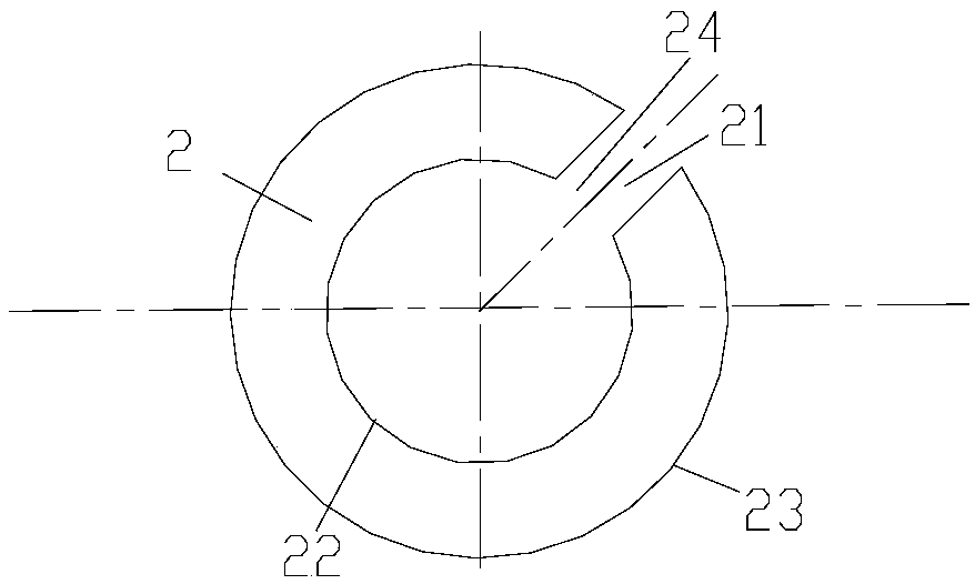
[0046] The inner rotor core 1 and the outer rotor core 2, the outer rotor core 2 can be sleeved on the outer periphery of the inner rotor core 2, and the inner rotor core 1 and the outer rotor core 2 A damping space for accommodating the damping material 4 can be formed between them;

[0047] The inner rotor core 1 is provided with a first groove 11 along the radial direction, and the outer rotor core 2 is also provided with a second groove 21 along the radial direction, and the first groove 11 can be connected with The second groove 21 is oppositely arranged;

[0048] It also includes a bridge iron core 3, which can be penetrated into the first groove 11 and the second groove 21 at the same time to form a circumferential gap between the inner rotor core 1 and the outer rotor core 2. relative positioning.

[0049]The present invention adopts the first groove p...


PUM


Abstract

The invention provides a vibration damping rotor iron core, a vibration damping rotor and an electric machine. The vibration damping rotor iron core comprises an inner rotor iron core and an outer rotor iron core. The outer rotor iron core can be sleeved on the outer periphery of the inner rotor iron core, and a vibration damping space containing vibration damping material can be formed between the inner rotor iron core and the outer rotor iron core. The inner rotor iron core is provided with a first groove along the radial direction, and the outer rotor iron core is also provided with a second groove along the radial direction, and the first groove can be arranged opposite to the second groove. Also included is a bridge core capable of simultaneously penetrating into the first groove andthe second groove to form a circumferential relative positioning of the inner rotor iron core and the outer rotor iron core. The invention can realize the limit of the vibration damping material on the circumference, strengthen the tangential force of the vibration damping material on the circumference, prevent the vibration damping material from falling off due to the force, ensure the reliability of the rotor when the rotor rotates at high speed, and strengthen the reliability of the motor.

Description

technical field [0001] The invention belongs to the technical field of motors, and in particular relates to a vibration-damping rotor iron core, a vibration-damping rotor and a motor. Background technique [0002] At present, in permanent magnet motors, in order to reduce the vibration when the motor is loaded, a vibration-damping material is added between the rotor and the shaft to achieve the purpose of reducing vibration; in the existing technology, the rotor core is usually divided into two parts : Inner rotor and outer rotor, design corresponding protrusions in the inner and outer rotors, place them symmetrically, and leave a certain gap, fill them with damping material and finally form a damping rotor, the details are as follows figure 1 shown. [0003] However, in the existing technology, there is no limit requirement for the vibration-damping material in the circumferential direction, and it is only guaranteed by the combination force with the inner and outer rotors...

Claims


Application Information

Patent Timeline
Patent Type & Authority Applications(China)
IPC IPC(8): H02K1/22H02K1/28
CPCH02K1/22H02K1/28H02K2213/03
Inventor 周成海姜洋白冰左家禹温海聪王周叶曹原
Owner GREE ELECTRIC APPLIANCES INC
Why Eureka
Try Eureka