

Reshaping station for blow molding machines without pressure pads
A molding station and blow molding technology, applied in the field of molding stations, can solve the problems of high cost, high cost, high expenditure, etc., and achieve the effect of avoiding rapid wear and tear
Active Publication Date: 2018-12-21
KRONES AG
View PDF3 Cites 0 Cited by
- Summary
- Abstract
- Description
- Claims
- Application Information
AI Technical Summary
Problems solved by technology
However, relatively high costs are incurred due to the need for pressure pads to achieve a flush and positive engagement of the blow mold, e.g. for supplying compressed air to the pressure pads
Tubing and pressure pad seals are also quite expensive
In addition, comparatively high machining costs are required for the control of the pressure pad and, due to faults and severe wear, high outlays are also required
Method used
View moreImage
Smart ImageViewing Examples


Examples
Embodiment Construction
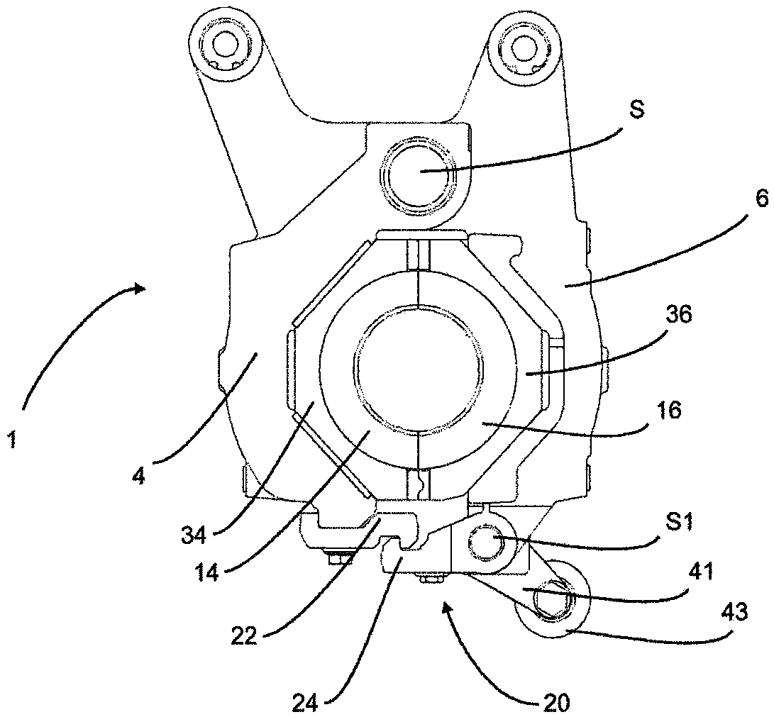
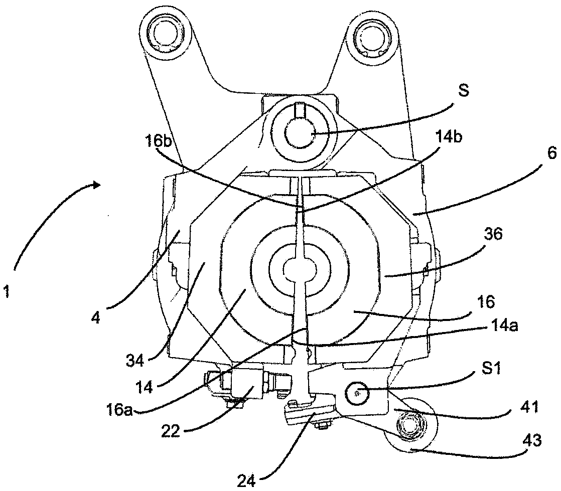
[0051] exist figure 1 A forming station 1 according to the invention is shown in . The forming station 1 has two side supports 4 and 6 . They are rotatable about the main axis S relative to each other. In this case, both side supports may rotate about this main axis. It is also possible that only one of the two side supports rotates about the main axis. It is also conceivable to provide two axes parallel to each other about which the two side supports rotate. Here, the main axis S or the corresponding rotational axis runs perpendicular to the drawing plane. The mold shells 34 and 36 are each arranged on two blow mold supports. The blow mold sides 14 and 16 are arranged successively on these mold shells 34 and 36 .
Login to View More PUM
 Abstract
The invention relates to a reshaping station (1) for reshaping plastic preforms (10) into plastic containers. The reshaping station (1) has two lateral part supports (4, 6) for supporting lateral parts (14, 16) of a blow mold and preferably a base part support for supporting a base part of the blow mold. The lateral parts (14, 16) and the base part (18) of the blow mold together form a cavity (15)within which the plastic preforms (10) can be reshaped into the plastic containers by applying a flowable medium. At least one of the two lateral part supports can be pivoted relative to the other lateral part support with respect to a specified main axis (S) in order to open and / or close the blow mold, and the reshaping station has a locking mechanism in order to lock one lateral part support (4) with the other lateral part support (6) in a closed state of the blow mold. The locking mechanism (20) has a first locking element (22) which can be pivoted with respect to a specified pivot axis (S1) and which engages into a second locking element (24) in order to lock the lateral part supports. According to the invention, at least one of the two locking elements has a first contact surface (26) which is suitable for interacting with a second contact surface (28) of the second locking element (24) when locking with the second locking element (24). At least one of the contact surfaces is designed such that the two lateral part supports (4, 6) are forced against each other during a pivoting process of the first locking element (26) with respect to the pivot axis (S1) in the direction of the second locking element (28).
Description
technical field [0001] The invention relates to a forming station for forming plastic parisons into plastic containers. This molding station, which can be used as part of a blow molding machine, is used for the production of plastic bottles. In this case, heated plastic parisons are introduced into the inlet of the blow mold and formed there by blowing air into plastic containers, in particular plastic bottles. For this purpose, these molding stations usually have blow mold supports for supporting the parts of the blow mold. The plastic parison is introduced into the blow mold, the mold is closed and the plastic parison is allowed to expand. Background technique [0002] In this case, it is known in the prior art that especially the point where the sides of the blow mold touch each other is critical in the production of plastic parisons and that this creates a seam on the finished bottle. Various procedures for maintaining these seams as small seams are known in the prior...
Claims
Login to View More Application Information
Patent Timeline
 IPC IPC(8): B29C49/48B29C49/56B29C49/06B29L31/00
CPCB29L2031/7158B29C49/06B29C49/48B29C2049/4892B29C2049/566B29C49/56B29C49/4205B29C2949/0715
Inventor托马斯·菲利普托马斯·斯皮策
OwnerKRONES AG