
Anti-impact reinforcing structure of debris flow retaining dam

A technology for strengthening structures and debris flow. It is applied in hydraulic engineering, marine engineering, coastline protection, etc. It can solve the problem of inability to resist large debris flow erosion and impact of large rocks, poor integrity, and insufficient strength of the protective tank and the end wall of the protective tank. Advanced problems, to achieve the effect of increasing value, small investment, and protecting weak positions

Pending Publication Date: 2019-09-10
彭必建
View PDF0 Cites 3 Cited by
  • Summary
  • Abstract
  • Description
  • Claims
  • Application Information

AI Technical Summary

Problems solved by technology

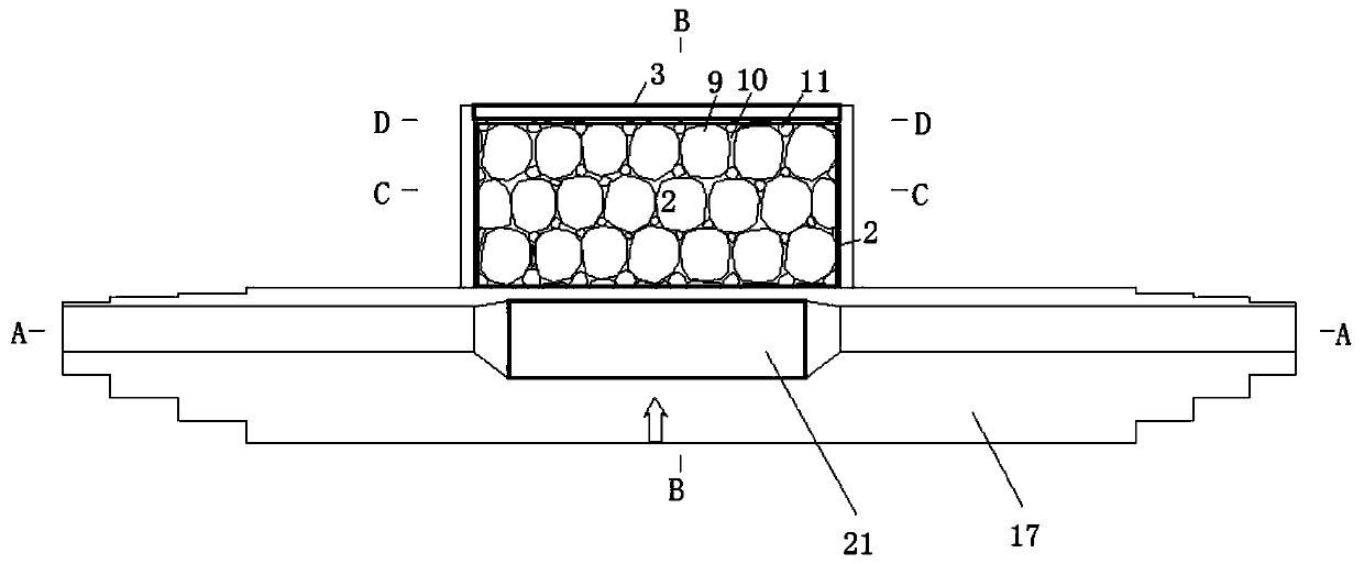
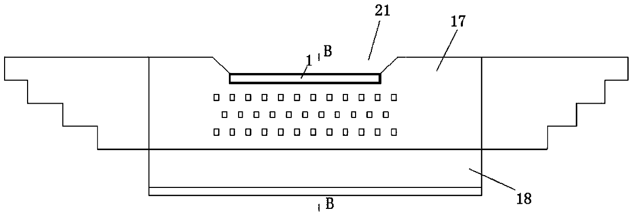
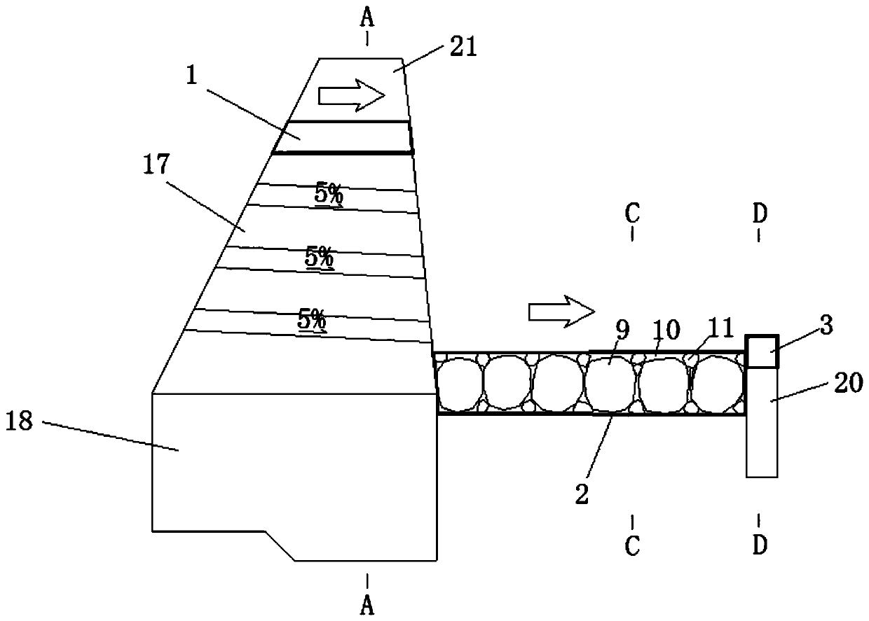
[0003] In summary, in order to solve the problem that the overflow outlet of the retaining dam, the apron and the end wall of the apron are not high in strength, the integrity is not strong, and they cannot resist the erosion of large debris flows and the impact of large rocks, the technology to be solved by the present invention The problem is to provide an anti-scour reinforcement structure for debris flow retaining dams. Aiming at the three weak and easily damaged positions of the retaining dam overflow, apron and apron end wall, a single reinforcement structure design scheme is formed from upstream to downstream to form a combined system to achieve The purpose of protecting the overflow outlet and foundation of the retaining dam and prolonging the service life of the dam

Method used


Image

  • Anti-impact reinforcing structure of debris flow retaining dam
  • Anti-impact reinforcing structure of debris flow retaining dam
  • Anti-impact reinforcing structure of debris flow retaining dam

Examples


Embodiment Construction

[0035] The principles and features of the present invention are described below in conjunction with the accompanying drawings, and the examples given are only used to explain the present invention, and are not intended to limit the scope of the present invention.

[0036] Such as Figure 1-5 As shown, a debris flow retaining dam anti-scour reinforcement structure includes a retaining dam body 17 , a retaining dam foundation 18 and a retaining dam overflow 21 . The dam body 17 is built on the dam foundation 18, and the dam overflow opening 21 is provided in the middle of the top. It also includes a reinforcement unit 1 for the overflow outlet of the dam, a reinforcement unit 2 for the apron and a reinforcement unit 3 for the end wall of the apron, the reinforcement unit 1 for the overflow outlet of the dam is built on the dam body 17 and It forms an integral body with the dam body 17, and the reinforcement unit 1 of the dam overflow opening is located at the position of the fl...


PUM

PropertyMeasurementUnit
Diameteraaaaaaaaaa
Diameteraaaaaaaaaa

Abstract

The invention relates to an anti-impact reinforcing structure of a debris flow retaining dam. The anti-impact reinforcing structure comprises a retaining dam body, a retaining dam foundation and a retaining dam overflow port, and further comprises a retaining dam overflow port reinforcing monomer, an apron reinforcing monomer and an apron end wall reinforcing monomer; the retaining dam overflow port reinforcing monomer is located on a bottom flow-passing surface of the retaining dam overflow port to protect the flow-passing surface of the retaining dam overflow port; and the front end of the apron reinforcing monomer is connected with the bottom of the retaining dam body, and the tail end of the apron reinforcing monomer rearwards extends by the preset distance and then is connected with the apron end wall reinforcing monomer to protect the retaining dam foundation. The anti-impact reinforcing structure has the beneficial effects that harm of debris flow flushing quick abrasion and boulder impact notch forming is prevented, the purpose of protecting the weak position is achieved, the reinforcing structure is less in investment, the service time of the retaining dam can be prolonged, and the value of governance engineering is improved greatly.

Description

technical field [0001] The invention relates to the technical field of mud-rock flow disaster control engineering, in particular to an anti-scour reinforcement structure of a mud-rock flow retaining dam. Background technique [0002] The overflow outlet is located in the middle of the retaining dam body, the apron is located in the foundation area downstream of the overflow outlet of the retaining dam, and the end wall of the apron is located at the downstream end of the apron. The overflow outlet, apron and apron end wall are the weakest and most vulnerable areas of the retaining dam. The existing retaining dam reinforcement schemes are generally only for the retaining dam overflow. Although the apron project is designed to protect the retaining dam foundation, no special design is adopted. The structure is reinforced, and it is easy to be damaged by debris flow, which will lead to the damage and failure of the retaining dam. The reinforcement of the overflow outlet of the...

Claims


Application Information

Patent Timeline
IPC IPC(8): E02B7/02E02B8/00
CPCE02B7/02E02B8/00
Inventor 彭必建
Owner 彭必建
Learn More