Compressor and heat cycle system

一种压缩机、压缩部的技术,应用在压缩机、照明和加热设备、制冷机等方向,达到防止自分解反应、防止火花的效果

Active Publication Date: 2018-12-21
AGC INC
View PDF15 Cites 1 Cited by
  • Summary
  • Abstract
  • Description
  • Claims
  • Application Information

AI Technical Summary

Problems solved by technology

[0007] In addition, it is known that this HFO-1123 will self-decompose under high temperature or high pressure when used alone if there is an ignition source

Method used


Image

  • Compressor and heat cycle system
  • Compressor and heat cycle system
  • Compressor and heat cycle system

Examples


Embodiment Construction

[0032] Hereinafter, embodiments for carrying out the present invention will be described with reference to the drawings.

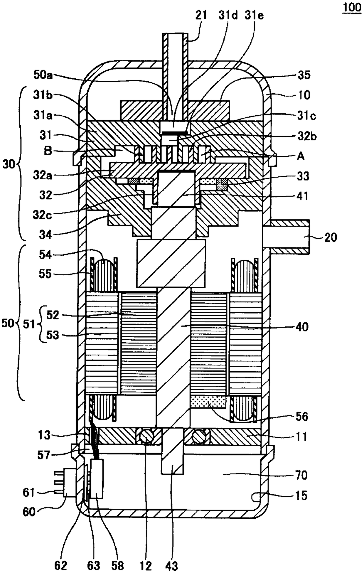
[0033] figure 1 It is a sectional view showing the configuration of an example of the compressor 100 according to the embodiment of the present invention. The compressor of the present invention can use various types of compressors including scroll compressors and rotary compressors as long as the compression part is arranged above and the electric part is arranged below. A type compressor will be described as an example of the compressor of the present invention.

[0034] The compressor 100 includes an airtight container 10 , a suction pipe 20 , a discharge pipe 21 , a compression unit 30 , a shaft 40 , an electric unit 50 , and a power supply terminal 60 .

[0035] The airtight container 10 functions as a casing of the compressor 100 and accommodates the compression unit 30 , the shaft 40 , the electric unit 50 , the power supply terminal 60 and the li...


PUM


Abstract

The present invention has: a sealed container (10); a compression part (30) that is provided to an upper portion of the inside of the sealed container and that compresses a working medium; an oil reservoir part (15) that is provided to a base portion of the inside of the sealed container and that stores a lubricating oil; an electric drive part (50) that is provided inside the sealed container between the compression part and the oil reservoir part and that drives the compression part; and a power source terminal (60) that is provided to pass through a wall surface of the sealed container in the region of the oil reservoir part, that can be connected to an external power source outside the sealed container, and that is electrically connected to the electric drive part inside the sealed container via a lead wire (57).

Description

technical field [0001] The present invention relates to compressors and thermal cycle systems. Background technique [0002] In the past, as a working medium for refrigerators, air conditioners, power generation systems (waste heat recovery power generation, etc.), working medium for latent heat transport devices (heat pipes, etc.), secondary cooling medium, etc. Chlorofluorocarbons (CFCs) such as chlorotrifluoromethane and dichlorodifluoromethane, and hydrochlorofluorocarbons (HCFCs) such as chlorodifluoromethane are used. However, CFCs and HCFCs have been pointed out to have an impact on the stratospheric ozone layer, and are currently restricted. [0003] For this reason, hydrofluorocarbons (HFCs) such as difluoromethane (HFC-32), tetrafluoroethane, and pentafluoroethane (HFC-125), which have little impact on the ozone layer, are used instead of the working medium for thermal cycles. CFCs and HCFCs. For example, R410A (approximately azeotropic mixed working medium with...

Claims


Application Information

Patent Timeline
Patent Type & Authority Applications(China)
IPC IPC(8): F04B49/10F04B39/00F04B39/12
CPCF04B39/00F04B39/023F04B39/0284F04B39/121F04B35/04F04C23/008F04C18/0215F04C2210/263F04C2210/26F04C2240/803F04C2240/809F04B39/12F04B49/10F04C29/0085F04C29/02F04C2240/30F04C2240/40F04C2270/70F25B31/026F25B2400/12F25B2500/06H02K5/136H02K5/225H02K7/14
Inventor 速水洋辉福岛正人高木洋一大塚哲央
Owner AGC INC
Why Eureka
Try Eureka