Supercharge Your Innovation With Domain-Expert AI Agents!

Loading and unloading mechanical arm of automatic dispensing production line

A technology of automatic dispensing and production line, which is applied to manipulators, devices that apply liquid to surfaces, coatings, etc. It can solve the problems of poor accuracy, expensive manipulators, and cumbersome structure, and achieve the effect of convenient maintenance.

Pending Publication Date: 2018-12-25
DONGGUAN UNIV OF TECH +1
View PDF0 Cites 0 Cited by
  • Summary
  • Abstract
  • Description
  • Claims
  • Application Information

AI Technical Summary

Problems solved by technology

[0002] At present, the domestic manipulators for the dispensing production line have problems of poor precision and complicated component design to a certain extent.
At the same time, imported manipulators are expensive and heavy in structure
The loading and unloading manipulators in the prior art mostly adopt the manipulator of the rectangular coordinate system, which can only realize 3 degrees of freedom, and the action space is small

Method used


Image

  • Loading and unloading mechanical arm of automatic dispensing production line
  • Loading and unloading mechanical arm of automatic dispensing production line
  • Loading and unloading mechanical arm of automatic dispensing production line

Examples


Embodiment 1

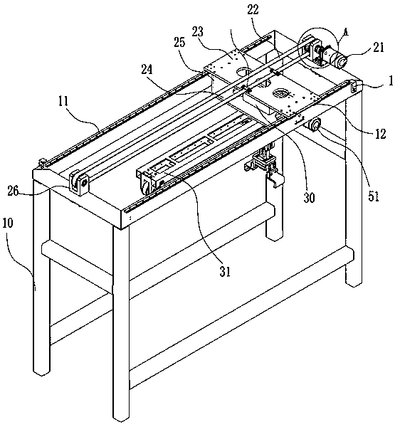
[0024] Such as figure 1 and as figure 2 As shown, the present invention provides a loading and unloading manipulator of an automatic glue dispensing production line. A first driving device 21 is provided on the frame 10. The first driving device 21 is a motor and corresponds to the first driving device 21 on the frame 10. A fixed seat 26 is provided at the position, and a transmission member 22 is connected to the fixed seat 26 and the first driving device 21. In this embodiment, the transmission member 22 is a transmission belt.

[0025] Such as figure 1 As shown, an X-axis motion platform is provided on the frame 10, and the X-axis motion platform is provided with a first connecting plate 23 and a second connecting plate 24, and the first connecting plate 23 and the second connecting plate 24 are stacked. The plate 23 and the second connecting plate 24 are connected by a fixing plate 25 .

[0026] Such as figure 1 As shown, the two sides that the first connection plate ...

Embodiment 2

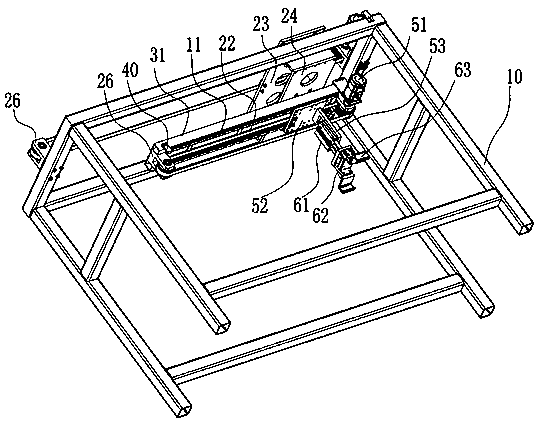
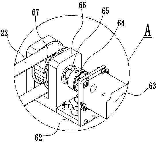
[0036] This embodiment is similar to Embodiment 1, the difference is that in this embodiment, the first driving device 21 is connected to the frame 10 through the installation base plate 62, the first driving device 21 is connected with a coupling 64, and the coupling 64 It is connected with the bearing 65 fixed by the bearing baffle 66 , and the coupling 64 is connected with a synchronous wheel 67 , and the synchronous wheel 67 is connected with the transmission member 22 .

[0037] Similarly, the second drive device 51 is connected to the support beam 31 through the installation base plate 62, the second drive device 21 is connected with a shaft coupling 64, and the shaft coupling 64 is connected with the bearing 65 fixed by the bearing baffle plate 66, while the shaft coupling 64 is connected with synchronous wheel 67, and synchronous wheel 67 is connected with transmission member 22.


PUM


Abstract

The invention relates to the technical field of dispensing devices, in particular to a loading and unloading mechanical arm of an automatic dispensing production line. The loading and unloading mechanical arm comprises a rack, wherein the rack is connected with a first drive device; the first drive device is connected with an X-axis motion platform through a transmission part; the X-axis motion platform is in sliding connection with the rack; the X-axis motion platform is connected with a Y-axis motion platform through a rotary device; a second drive device is arranged on the Y-axis motion platform; the second drive device is connected with a mechanical claw motion device through the transmission part; the mechanical claw motion device is equipped with a third drive device; and the third drive device is connected with a mechanical claw. The loading and unloading mechanical arm has the characteristics of being high in freedom and modularized in design.

Description

technical field [0001] The invention relates to the technical field of glue dispensing devices, and more specifically, to a loading and unloading manipulator of an automatic glue dispensing production line. Background technique [0002] At present, the domestic manipulators for the dispensing production line have problems of poor precision and complicated component design to a certain extent. At the same time, imported manipulators are expensive and heavy in structure. The loading and unloading manipulators in the prior art mostly adopt the manipulator of the rectangular coordinate system, which can only realize 3 degrees of freedom, and the action space is small. Contents of the invention [0003] In order to overcome at least one defect of the above-mentioned prior art, the present invention provides a loading and unloading manipulator of an automatic glue dispensing production line, which has the characteristics of high degree of freedom and modular design. [0004] I...

Claims


Application Information

Patent Timeline
IPC IPC(8): B05C13/02B25J11/00
CPCB05C13/02B25J11/0075
Inventor 郭建文孙振忠陈金宇叶国良曾志彬吴国洪李晓彦陈承志
Owner DONGGUAN UNIV OF TECH
Features
  • R&D
  • Intellectual Property
  • Life Sciences
  • Materials
  • Tech Scout
  • Unparalleled Data Quality
  • Higher Quality Content
  • 60% Fewer Hallucinations
Learn More