Welding installation process of rotor partition plates of rotary air preheater

An installation process and air preheater technology, applied in welding equipment, manufacturing tools, arc welding equipment, etc., can solve the problem of difficulty in meeting the installation quality requirements of the rotary air preheater rotor, affecting the output and economic operation of the unit, and adjusting the accuracy of the sealing gap. Reduce the problems such as avoiding the belt deviation, improve the adjustment accuracy, improve the output and economic operation.

Inactive Publication Date: 2018-12-25
POWERCHINA SEPCO1 ELECTRIC POWER CONSTR CO LTD
View PDF5 Cites 2 Cited by
  • Summary
  • Abstract
  • Description
  • Claims
  • Application Information

AI Technical Summary

Problems solved by technology

[0003] However, it is difficult to control the welding deformation of the partition plate of the rotary air preheater rotor by using the existing technology, so that the cylindrical rotor is deformed into an elliptical cylindrical shape, and the rotor is not parallel to produce friction when the rotor is running, and the shroud deviates; The adjustment accuracy of various sealing gaps of the rotary air preheater is reduced, and the air leakage is increased, which seriously affects the output and economic operation of the unit; and the welding deformation of the compartment partition makes it difficult to install the heat exchange elements and increase the construction period; it is difficult to meet the requirements of the rotary air preheater. Installation Quality Requirements for Preheater Rotor

Method used


Image

  • Welding installation process of rotor partition plates of rotary air preheater
  • Welding installation process of rotor partition plates of rotary air preheater

Examples


Embodiment

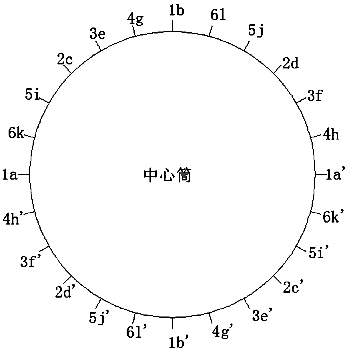
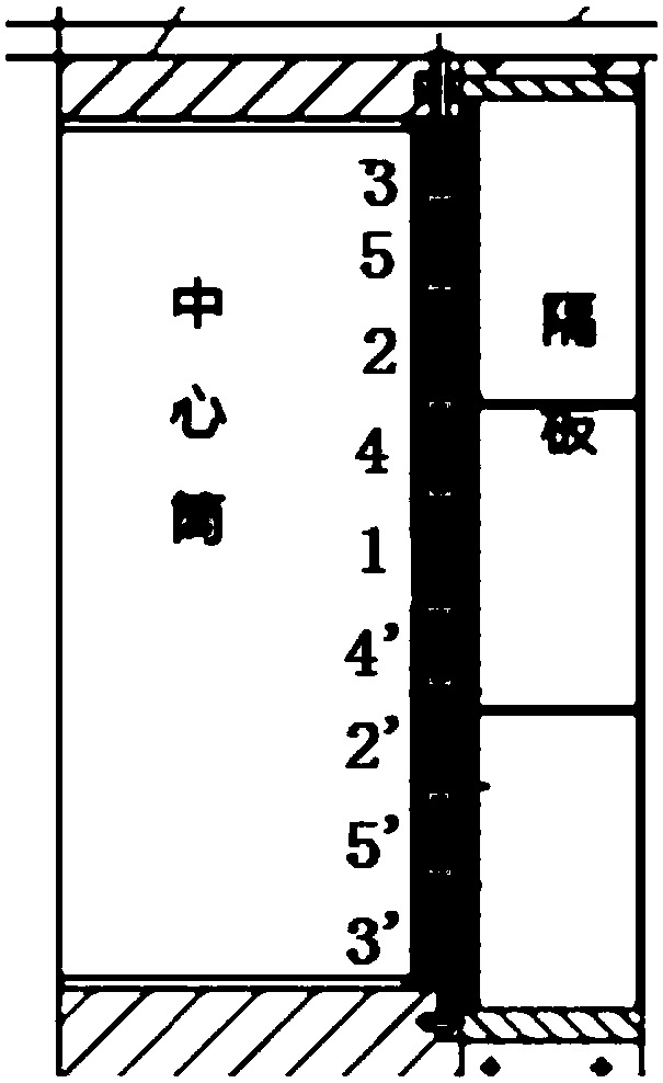
[0035] A welding and installation process for the rotor diaphragm of a rotary air preheater, including a central cylinder and six groups of diaphragms, each group of diaphragms includes four diaphragms, and the angle between two adjacent diaphragms of each group of diaphragms is 90°, such as figure 1 As shown, the welding of six sets of partitions includes the following steps:

[0036] (1) Preparation before welding: remove the rust, moisture and dirt within 20mm of the groove surface and both sides of the groove, and fully dry it, and prepare the arc striking plate and the arc extinguishing plate. Groove refers to the groove processed by the central cylinder and the partition on the part to be welded. The groove surface refers to the groove surface of the central cylinder and the partition. Cleaning the groove surface can reduce the occurrence of welding defects and improve the welding effect ;Prepare the arc striking plate and the arc extinguishing plate, which can avoid ar...


PUM


Abstract

The invention discloses a welding installation process of rotor partition plates of a rotary air preheater, and belongs to the technical field of installation of rotary air preheater rotors. The process includes the steps that (1) two partition plates symmetrically located on the two sides of a center cylinder in a first group of partition plates are welded to the wall of the center cylinder, andthe other two partition plates symmetrically located on the two sides of the center cylinder in the first group of partition plates are welded to the wall of the center cylinder; (2) each partition plate in a second group of partition plates is located between two adjacent partition plates in the first group of partition plates, and the second group of partition plates are welded according to thewelding sequence of the first group of partition plates; (3) N groups of partition plates located between the second group of partition plates and the first group of partition plates which are adjacent clockwise are uniformly distributed clockwise in the circumferential direction of the center cylinder; (4) N groups of partition plates located between the first group of partition plates and the second group of partition plates which are adjacent clockwise are uniformly distributed anticlockwise in the circumferential direction of the center cylinder. By means of the process, overall symmetry welding of the partition plates can be realized, and welding deformation in the prior art is reduced to the maximum.

Description

technical field [0001] The invention relates to the technical field of installation of a rotary air preheater rotor, in particular to a welding and installation process for a rotor partition of a rotary air preheater. Background technique [0002] With the development of electric power technology and the proposal of the national energy saving and emission reduction policy, the rotary air preheater with compact structure and light weight has been widely used in large capacity units in my country. The rotor of the rotary air preheater is mainly composed of a central tube, a fan The fan-shaped compartment is composed of two adjacent partitions that are evenly distributed radially around the circumference of the central cylinder. Due to the large size of the rotary air preheater rotor, it is usually necessary to weld and install the air preheater rotor on site. In the prior art, the installation of the rotor compartment of the rotary air preheater adopts a sequential installatio...

Claims


Application Information

Patent Timeline
Patent Type & Authority Applications(China)
IPC IPC(8): B23K9/02
CPCB23K9/0026B23K9/02
Inventor 王建勇于群张俭平庞继勇邵德让曲克刚
Owner POWERCHINA SEPCO1 ELECTRIC POWER CONSTR CO LTD
Why Eureka
Try Eureka