Vehicle travel control method, device and vehicle

A technology of vehicle driving and control methods, applied in the directions of signal devices, vehicle components, transportation and packaging, etc., can solve the problems of physical impact and discomfort of people in the vehicle, and achieve the effect of reducing discomfort

Active Publication Date: 2018-12-25
NEUSOFT REACH AUTOMOBILE TECH (SHENYANG) CO LTD
View PDF7 Cites 7 Cited by
  • Summary
  • Abstract
  • Description
  • Claims
  • Application Information

AI Technical Summary

Problems solved by technology

[0004] Especially, when the driver takes the braking action late, in order to prevent the vehicle from exceeding the stop line at the intersection, the driver will take a sudden braking action to ensure that the vehicle stops in a short distance and in a short time. The body will be subjected to a strong impact. At this time, the body of the occupants in the car will have a strong sense of discomfort due to the impact.

Method used


Image

  • Vehicle travel control method, device and vehicle
  • Vehicle travel control method, device and vehicle
  • Vehicle travel control method, device and vehicle

Examples


Embodiment 1

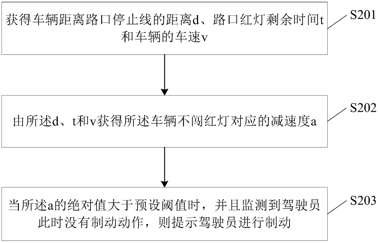
[0068] see figure 2 , which is a flowchart of the vehicle driving control method provided by the first embodiment of the application.

[0069] The vehicle driving control method provided by the embodiment of the present application includes:

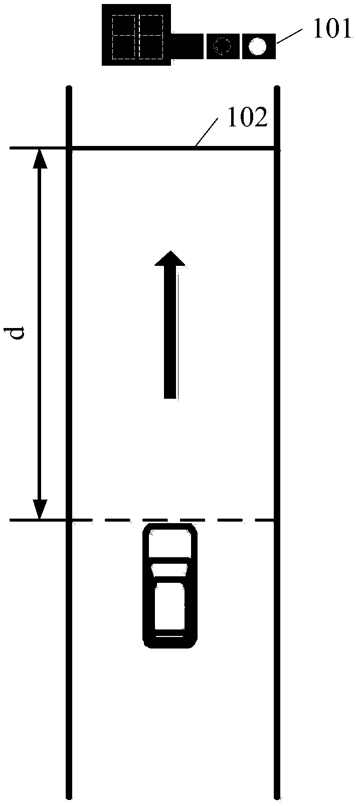
[0070] S201: Obtain the distance d of the vehicle from the stop line at the intersection, the remaining time t of the red light at the intersection, and the speed v of the vehicle;

[0071] When the vehicle passes through the intersection where the signal light is installed and the signal light is in the red light state, the vehicle should stop before the stop line and cannot exceed the stop line.

[0072] When the vehicle is approaching an intersection with a signal light installed, it needs to take corresponding actions according to the status of the signal light. When the signal light is in the red light state, the driver needs to take the braking action to ensure that the vehicle stops before the stop line and avoid running the re...

Embodiment 2

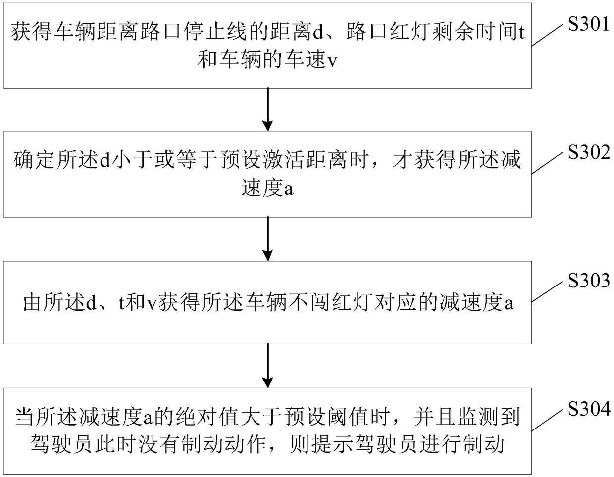
[0110] see image 3 , which is a flowchart of the vehicle driving control method provided in the second embodiment of the application.

[0111] The content of S301 is the same as that of S201, and will not be repeated here;

[0112] S302: The deceleration a is obtained only when it is determined that the d is less than or equal to a preset activation distance.

[0113] The preset activation distance is a preset distance for activating the vehicle travel control method. Moreover, the preset activation distance may be a parameter set when the vehicle leaves the factory, or a parameter set by the driver according to his own needs.

[0114] If there is no signal light on the road where the vehicle is driving, there is no stop line, so the distance d from the vehicle to the stop line at the intersection cannot be obtained. At this time, S303-S304 will not be performed; The relative size of the distance d from the intersection stop line and the preset activation distance: if the ...

Embodiment 3

[0135] see Figure 5 , which is a schematic structural diagram of the vehicle driving control device provided in the third embodiment of the application.

[0136] The vehicle driving control device provided by the embodiment of the present application includes:

[0137] an obtaining unit 501, configured to obtain the distance d of the vehicle from the stop line at the intersection, the remaining time t of the red light at the intersection, and the speed v of the vehicle;

[0138] a deceleration calculation unit 502, configured to obtain the deceleration a corresponding to the vehicle not running a red light from the d, t and v;

[0139] The decision-making unit 503 is configured to prompt the driver to brake when the absolute value of the deceleration a is greater than a preset threshold value and it is detected that the driver has no braking action at this time.

[0140] For the convenience of description and for those skilled in the art to better understand the technical s...


PUM


Abstract

The invention discloses a vehicle travel control method, a device and a vehicle. The vehicle traveling control method comprises the following steps: obtaining a distance d of the vehicle from an intersection stop line, a remaining time t of a red light at the intersection and a vehicle speed v of the vehicle; Obtaining a deceleration a corresponding to the vehicle not running a red light from thed, t and v; When the absolute value of a is greater than a preset threshold value and the driver is detected to have no braking action at this time, the driver is prompted to brake. As that vehicle move towards an intersection where signal light are installed and the signal lights are in a red light condition, By calculating the deceleration a and detecting the driver's braking action, the methodcan prompt the driver to brake in time, thus assisting the driver to control the vehicle to stop at the red light intersection smoothly and reducing the discomfort of the body.

Description

technical field [0001] The present invention relates to the technical field of automotive electronics, and in particular, to a vehicle driving control method, device and vehicle. Background technique [0002] With the popularity of automobiles, the driving safety and driving comfort of vehicles have gradually attracted attention. When the vehicle travels to the intersection where the signal light is installed, the driver needs to select the corresponding driving action according to the state of the signal light. When the signal light is red, the driver should brake in time to make the vehicle stop before the stop line at the intersection. [0003] Due to inertia, the body of the occupant will maintain a certain speed as the vehicle travels. When the vehicle brakes, the occupants in the vehicle will be impacted by inertia. The greater the deceleration of the vehicle when braking, the greater the impact on the occupants in the vehicle, and the stronger the discomfort caused...

Claims


Application Information

Patent Timeline
Patent Type & Authority Applications(China)
IPC IPC(8): B60Q9/00B60R16/023
CPCB60Q9/00B60R16/023
Inventor 卫璐刘威
Owner NEUSOFT REACH AUTOMOBILE TECH (SHENYANG) CO LTD
Why Eureka
Try Eureka