Eureka AIR delivers breakthrough ideas for toughest innovation challenges, trusted by R&D personnel around the world.

An Ultrasonic Comprehensive Factor Pattern Recognition Detection Method for Sleeve Grouting Fullness

A comprehensive factor, sleeve grouting technology, applied in the direction of material analysis, measuring device, instrument, etc. using sonic/ultrasonic/infrasonic waves, it can solve the problems of difficult grouting density detection, difficult final determination by testers, inconsistency, etc., and achieve good results. Detect the effect of the effect

Active Publication Date: 2021-03-02
北京市康科瑞工程检测技术有限责任公司 +1
View PDF6 Cites 0 Cited by
  • Summary
  • Abstract
  • Description
  • Claims
  • Application Information

AI Technical Summary

Problems solved by technology

However, in the grouting fullness test, due to the relatively small scale of the grouting layer relative to the propagation path, the air layer defect caused by insufficient grouting or even no grouting has a great impact on the safety of the structure, but it is still a small-scale defect as an acoustic defect. Therefore, in many cases, the abnormal position measurement results determined by the acoustic parameters of sound velocity and first wave amplitude are not consistent, and there may even be obvious or even opposite conclusions. Since there is no unified quantitative parameter, the tester difficult to make a final decision
[0015] This shows that although the ultrasonic method has advantages in principle compared with other detection technologies, it is difficult to complete the detection of grouting density based on the conventional ultrasonic detection defect method, and it is necessary to explore new ultrasonic detection technology methods

Method used

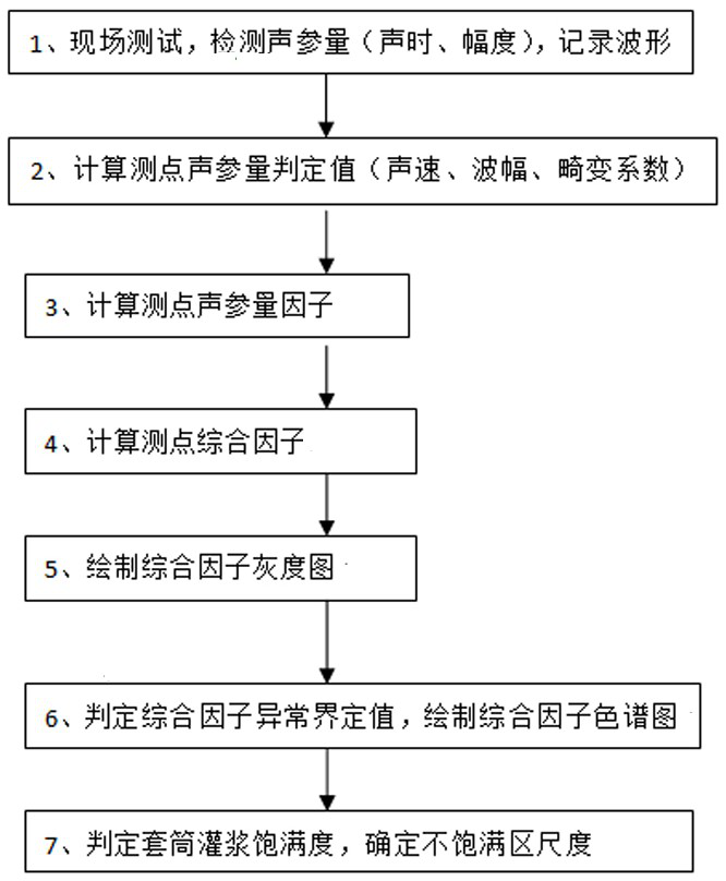
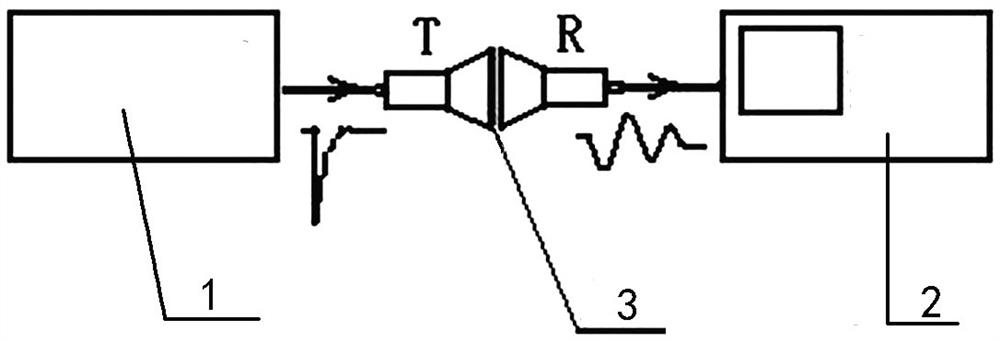
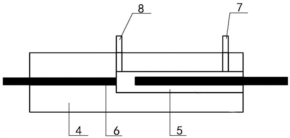

Image

  • An Ultrasonic Comprehensive Factor Pattern Recognition Detection Method for Sleeve Grouting Fullness
  • An Ultrasonic Comprehensive Factor Pattern Recognition Detection Method for Sleeve Grouting Fullness
  • An Ultrasonic Comprehensive Factor Pattern Recognition Detection Method for Sleeve Grouting Fullness

Examples


Embodiment Construction

[0081] Hereinafter, an embodiment of an ultrasonic comprehensive factor pattern recognition detection method for sleeve grouting plumpness according to the present invention will be described with reference to the accompanying drawings. The examples described here are specific specific implementations of the present invention, and are used to illustrate the concept of the present invention. They are all explanatory and exemplary, and should not be construed as limiting the implementation of the present invention and the scope of the present invention. In addition to the embodiments described here, those skilled in the art can also adopt other obvious technical solutions based on the claims of the application and the contents disclosed in the description, and these technical solutions include adopting any obvious changes made to the embodiments described here. Replacement and modified technical solutions.

[0082] The accompanying drawings in this specification are schematic di...


PUM


Abstract

The present invention proposes an ultrasonic comprehensive factor pattern recognition and detection method for sleeve grouting fullness, and for the first time proposes a calculation method of "spectral modulus" of "distortion coefficient" representing the degree of waveform distortion, which is used as a quantified acoustic parameter representing the degree of waveform distortion , and at the same time put forward the "comprehensive factor" calculation method and the "comprehensive factor image recognition method" grouting fullness judgment method, which adopts a completely different defect recognition and judgment idea from the conventional probability method, without increasing the detection cost and affecting the detection efficiency. Under the premise of the test, the technical index requirements for the sleeve grouting fullness test are met. And it also has good test results for the internal defect detection of other concrete structures, especially for the complex component parts of the beam-slab-column joints and the components with too dense internal reinforcement. , It also provides technical basis and equipment support for engineering construction and standard formulation.

Description

technical field [0001] The invention relates to the technical field of quality control and detection of assembled concrete buildings, in particular to an ultrasonic comprehensive factor pattern recognition and detection method for the fullness of sleeve grouting, which is an ultrasonic method for sleeve grouting connection of assembled concrete structures. The technology of non-damage detection of the grouting fullness inside the reinforced sleeve of the method. Background technique [0002] Prefabricated concrete structure means that some or all of the components and parts are produced in the prefabricated factory, and then transported to the construction site. The components are assembled by reliable connection methods and installation machinery to form a structure with the designed load-bearing function. Compared with cast-in-place structures, prefabricated construction has the advantages of convenient construction, fast project progress, little impact on the surrounding ...

Claims


Application Information

Patent Timeline
Patent Type & Authority Patents(China)
IPC IPC(8): G01N29/024
CPCG01N29/024G01N2291/02433
Inventor 何国胜濮存亭
Owner 北京市康科瑞工程检测技术有限责任公司
Why Eureka
Eureka Blog
Learn More