An automatic laminating device for transformer iron core

A transformer core and laminated device technology, which is applied in the manufacture of inductors/transformers/magnets, electrical components, circuits, etc., can solve the problems of large labor costs, heavy workload, and low production efficiency, so as to ensure beautiful appearance and improve Production efficiency and production cost reduction effects

Pending Publication Date: 2018-12-25
ZHEJIANG JIANGSHAN TRANSFORMER CO LTD
View PDF0 Cites 2 Cited by
  • Summary
  • Abstract
  • Description
  • Claims
  • Application Information

AI Technical Summary

Problems solved by technology

Moreover, the transformer core is often not a single winding post. For example, it usually needs to form a "day"-shaped winding skeleton. Therefore, it needs to be stacked and spliced ​​by five groups of silicon steel sheets, and the width and shape of the silicon steel sheets in each group Different, after each group of silicon steel sheets is stacked, its longitudinal section forms a spindle-shaped structure. Therefore, the structure of the transformer core is complex, the number of silicon steel sheets is very large, and the weight of the finished product of a large transformer core is very large.
[0003] Existing transformer manufacturers usually produce iron cores by manually stacking silicon steel sheets one by one. It is conceivable that manual lamination has the following inevitable defects: due to the large number of silicon steel sheets, workers usually need to stack them one by one. The workload is huge, and the workers cannot work 24 hours a day, and the production efficiency is low; usually 2-4 workers are required to perform the lamination work of an iron core at the same time, resulting in huge labor costs in the factory, and the lamination work is very uneconomical; Since manual work cannot guarantee the concentration of attention at all times, it is very easy to have uneven laminations, which affects the appearance of the iron core and even the quality of the transformer.

Method used


Image

  • An automatic laminating device for transformer iron core
  • An automatic laminating device for transformer iron core
  • An automatic laminating device for transformer iron core

Examples


Embodiment Construction

[0033] Below in conjunction with each accompanying drawing, the present invention is described in detail.

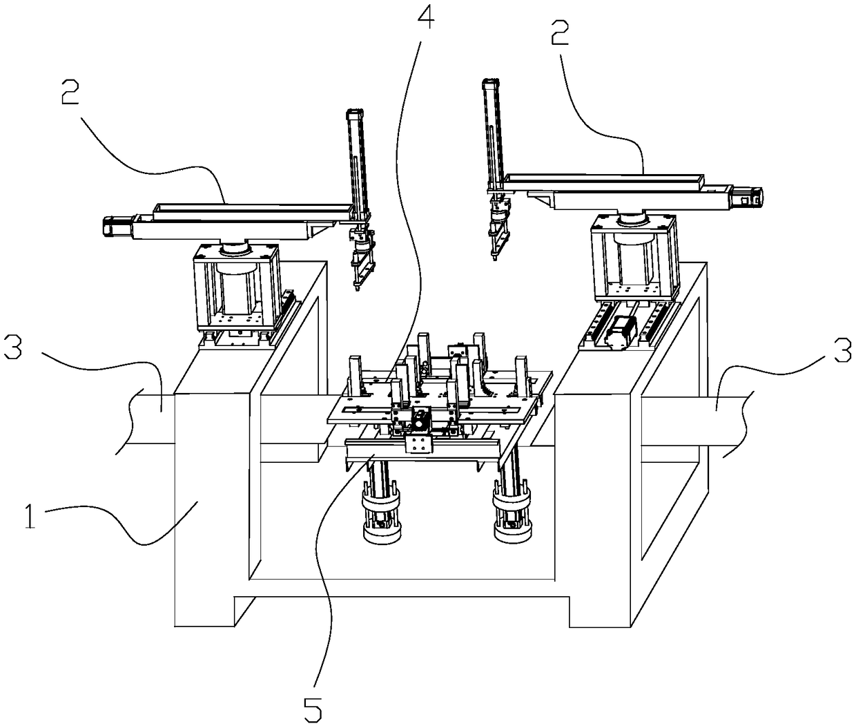
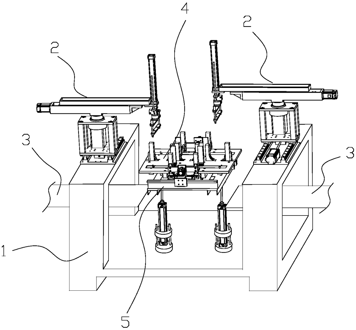
[0034] to combine figure 1 with figure 2 , the automatic lamination device of the present invention includes a support 1 , a pick-and-place mechanism, a transmission mechanism 3 , a lamination platform 4 and a lifting mechanism 5 , preferably, the pick-and-place mechanism is a five-axis manipulator 2 . A five-axis manipulator 2 is installed on the two installation platforms of the bracket 1, and a lifting mechanism 5 is installed between the two installation platforms. The lamination platform 4 is placed on the lifting mechanism 5, and the transmission mechanism 3 is used for feeding In order to stack the lamination platform 4 of the silicon steel sheet and send out the lamination platform 4 of the silicon steel sheet, the transmission mechanism 3 passes through the through hole of the mounting platform of the support 1 and is connected with the lifting mechanism 5 . ...


PUM


Abstract

The invention relates to the technical field of automation equipment for transformer production, in particular to an automatic laminating device for transformer iron core. The laminating device includes a holder, a take-off and release mechanism, A conveyor mechanism and a lamination platform, the picking and placing mechanism and the conveying mechanism are fixed on the bracket, The pick-and-place mechanism is used for grasping the lamination and stacking on the lamination platform, the lamination platform is placed on the bracket and can move along the lamination direction of the pick-and-place mechanism, and the conveying mechanism is used for feeding the lamination platform to the lamination range of the pick-and-place mechanism and sending out the lamination platform after the lamination is completed. The device can be operated 24 hours a day, and the lamination speed is higher than that of manual lamination, thereby greatly improving the production efficiency; After the initial investment in the production line, there is no need to spend on lamination workers in the later period, which greatly reduces the production cost; The quality of lamination is stable and the error probability is much lower than that of manual lamination, which ensures the beautiful appearance of iron core and the stability of transformer quality.

Description

technical field [0001] The invention relates to the technical field of automation equipment for transformer production, in particular to an automatic lamination device for transformer cores. Background technique [0002] The transformer iron core is the support frame used to wind the transformer coil winding, while the existing iron core is actually a structure with a fixed shape formed by laminating multiple silicon steel sheets. Moreover, the transformer core is often not a single winding post. For example, it usually needs to form a "day"-shaped winding skeleton. Therefore, it needs to be stacked and spliced ​​by five groups of silicon steel sheets, and the width and shape of the silicon steel sheets in each group Different, after each group of silicon steel sheets is laminated, its longitudinal section forms a spindle-shaped structure. Therefore, the structure of the transformer iron core is complex, the number of silicon steel sheets is very large, and the weight of the...

Claims


Application Information

Patent Timeline
IPC IPC(8): H01F41/02
CPCH01F41/0233
Inventor 姜振军
Owner ZHEJIANG JIANGSHAN TRANSFORMER CO LTD
Why Eureka
Try Eureka