
Integrally formed inductor and manufacture process thereof

An inductor and integrated technology, applied in the field of inductors, can solve the problems that affect the overall size and overall appearance of the inductor, affect the normal connection, and have no fixed structure, so as to achieve better connection quality, ensure the appearance size and aesthetics, size, etc. The effect of better control

Inactive Publication Date: 2012-05-23
奋发电子(东莞)有限公司
View PDF5 Cites 0 Cited by
  • Summary
  • Abstract
  • Description
  • Claims
  • Application Information

AI Technical Summary

Problems solved by technology

[0004] However, the aforementioned conventional one-piece inductor still has many shortcomings in its own structure and performance.
First of all, when the coil and the electrode piece are connected by welding, the free end of the coil and the electrode piece are simply overlapped together for welding operation, and there is no corresponding fixed structure, which makes the connection strength between the coil and the electrode piece weak and easy Looseness will affect the normal connection, and even cause the product to be scrapped
Secondly, the welding method between the free end of the coil and the electrode sheet is manual welding, which is not only cumbersome and inefficient, but also prone to false welding, resulting in poor conductivity and high impedance.
Furthermore, since the welding spot between the free end of the coil and the electrode piece is located in the groove of the magnetic core shell, in the actual welding process, the solder paste often overflows the groove and flows onto the surface of the magnetic core shell, so that Affects the form factor and overall appearance of the inductor

Method used


Image

  • Integrally formed inductor and manufacture process thereof
  • Integrally formed inductor and manufacture process thereof
  • Integrally formed inductor and manufacture process thereof

Examples


Embodiment Construction

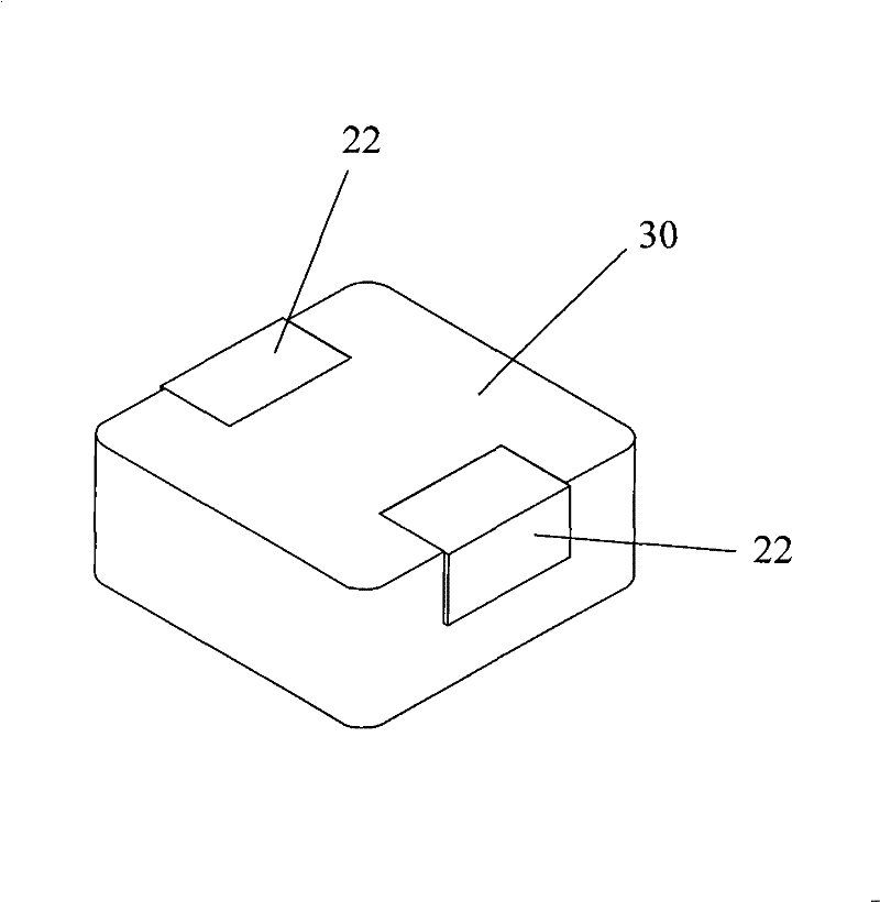
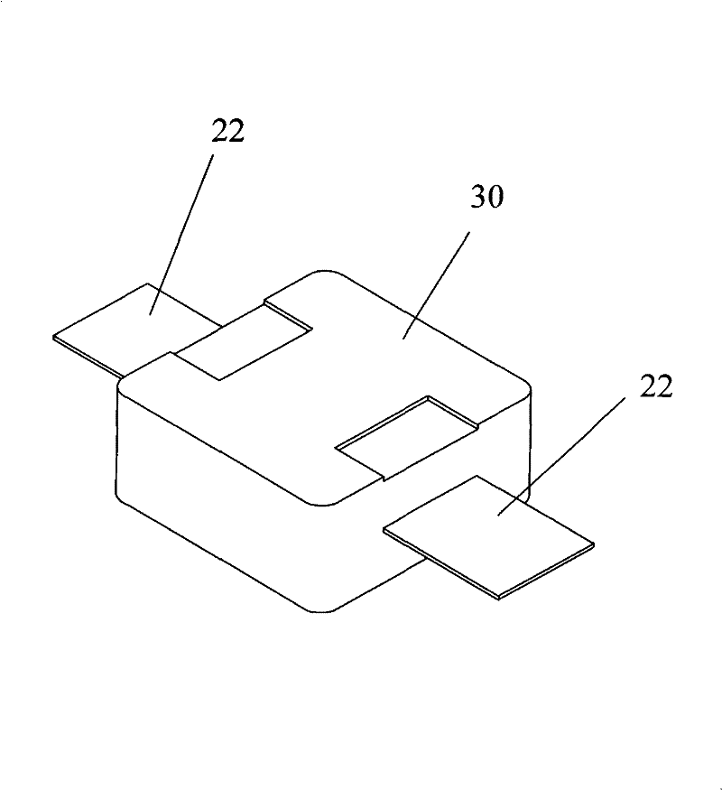
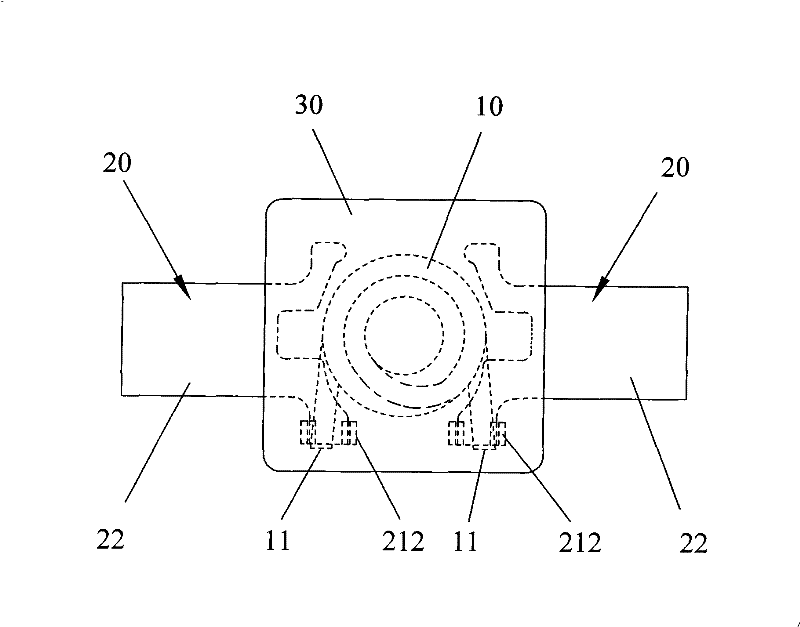
[0047] First, please refer to Figure 1 to Figure 4As shown, it shows the specific structure of the preferred embodiment of the present invention, including a coil 10, two electrode feet 20 and a magnetic solid body 30 made by pressing powder molding, and the coil 10 is embedded in the magnetic solid body 30 Inside, the first ends 21 of the two electrode feet 20 are embedded in the magnetic solid body 30 to maintain an electrical gap and are electrically connected to the two pins 11 of the coil 10, and the second ends 22 of the two electrode feet 20 extend out of the magnetic solid body. The body 30 is bent and tightly attached to the surface of the magnetic solid body 30 . The material of the magnetic solid body 30 can be soft magnetic alloy powder or insulating iron powder.

[0048] Such as Figure 4 and combine image 3 , the electrode foot 20 is a sheet-like structure, the middle of the first end 21 of the electrode foot 20 is provided with a positioning notch 215, and ...


PUM


Abstract

The invention discloses an integrally formed inductor and a manufacture process thereof, comprising a coil, two electrode pins and a magnetic solid body formed by press powder. The coil is embedded in the magnetic solid body; first end parts of the two electrode pins are embedded in the magnetic solid body with electric clearances and are electrically connected with two pins of the coil; second end parts of the two electrode pins are bent and tightly attached to the surface of the magnetic solid body; the first end part of each electrode pin is provided with two vertical clamping pieces whichare integrally bent and formed; and the pins of the coil are clamped in the two vertical clamping pieces and are welded and electrically connected. By adopting the structure, the connection strength between the coil and the electrode pins is enhanced, the connection reliability between the coil and the electrode pins is ensured, thereby avoiding the quality hidden trouble and finally greatly improving the quality of products. In addition, through reasonably arranging the manufacture process of the inductor and simplifying the manufacture flow, the invention ensures that the manufacture of theinductor can be finished automatically, simply and fast, and has the remarkable characteristics of high efficiency and high quality.

Description

technical field [0001] The invention relates to the field of inductors for electronic devices, in particular to an integrated inductor with better quality, more beautiful appearance, and higher manufacturing efficiency and its manufacturing process. Background technique [0002] Inductors, also known as inductance coils, are one of the basic components of electronic circuits. In an AC circuit, the inductance coil has the ability to hinder the passage of AC, but it has no effect on DC (except for the DC resistance of the coil itself), so the inductance coil plays the role of blocking, step-down, cross-connection coupling and load etc. When the inductance and capacitance cooperate, it can be used for tuning, filtering, frequency selection, decoupling, etc. [0003] In terms of the development process of inductors, the early inductors were mainly wire-wound inductors. The structure of wire-wound inductors is to wind the enameled wire around the outside of the magnetic conduct...

Claims


Application Information

Patent Timeline
Patent Type & Authority Patents(China)
IPC IPC(8): H01F17/04H01F27/29H01F27/24H01F41/00
Inventor 马德邦饶金火
Owner 奋发电子(东莞)有限公司
Learn More