Straw breaker multi-roller linkage feeding mechanism

A technology of cutting grass cutter and grass lowering roller, applied in the field of agricultural machinery, can solve problems such as difficulty in meeting actual use requirements, and achieve the effect of meeting fineness and diversification requirements, and being flexible and convenient to use.

Inactive Publication Date: 2018-12-28
凤城市联发农机制造有限公司
View PDF5 Cites 1 Cited by
  • Summary
  • Abstract
  • Description
  • Claims
  • Application Information

AI Technical Summary

Problems solved by technology

[0002] Hay cutter usually includes several parts such as frame, upper hood, motor, cutter head, gearbox, feeding mechanism, etc., wherein the cutter head is driven to rotate by the motor, and the cutter head shaft transmits power through the gearbox to drive the feeding mechanism. The upper grass roller and the lower grass roller rotate, but the feeding mechanism in the prior art only has one upper grass roller and one lower grass roller. The grass roller is connected, and the lower output shaft is connected with the lower grass roller, so as to drive the upper and lower grass rollers to rotate synchronously and reversely to realize feeding. However, with the development of animal husbandry technology, users have higher and higher requirements for the precision and diversification of livestock feed processing. , the feeding structure of the traditional hay cutter with only one upper grass roller and one lower grass roller has been difficult to meet the actual use requirements

Method used


Image

  • Straw breaker multi-roller linkage feeding mechanism
  • Straw breaker multi-roller linkage feeding mechanism
  • Straw breaker multi-roller linkage feeding mechanism

Examples


Embodiment Construction

[0021] The present invention will be described in further detail below in conjunction with the accompanying drawings.

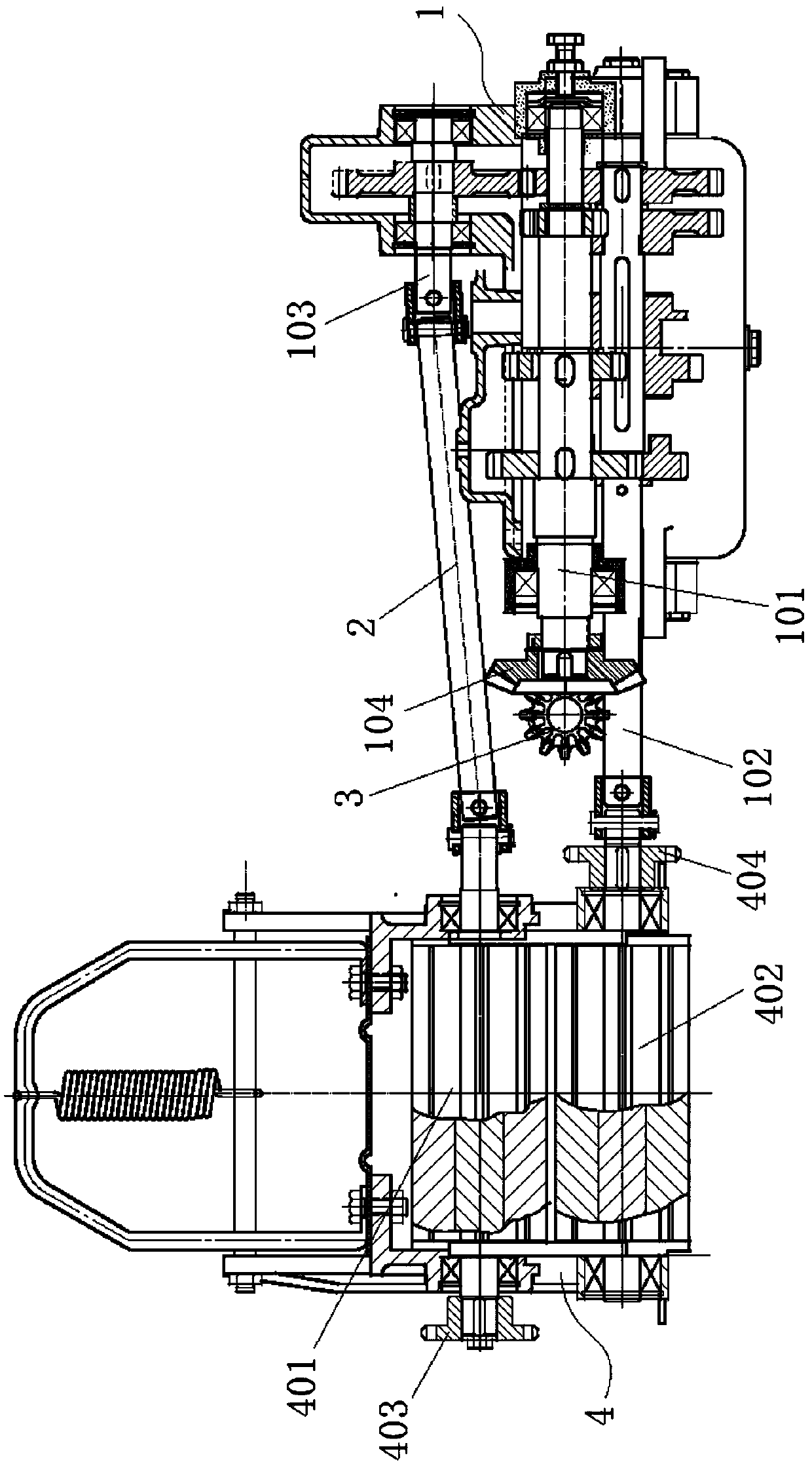
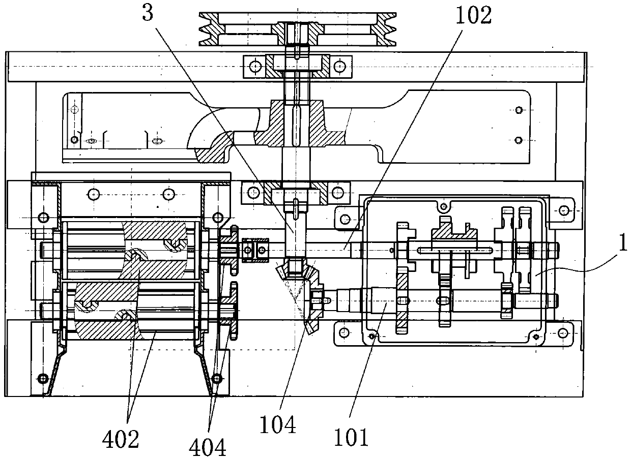
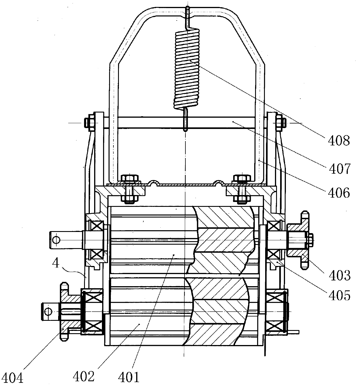
[0022] Such as Figure 1-7 Shown, the present invention comprises feeding support 4, upper grass roller 401, lower grass roller 402, upper sprocket chain assembly 403, lower sprocket chain assembly 404 and chain adjustment mechanism 5, wherein two upper grass rollers 401 are movably Set on the upper part of the feeding support 4, two lower grass rollers 402 are arranged on the lower part of the feeding support 4, the ends of the two upper grass rollers 401 are connected through the upper sprocket chain assembly 403, and the ends of the two lower grass rollers 402 pass through The lower sprocket chain assembly 404 is connected, and the upper sprocket chain assembly 403 and the lower sprocket chain assembly 404 are separately arranged on both sides of the feed support 4, and chains are arranged on both sides of the feed support 4. Adjustment mechanism 5.

[0...


PUM


Abstract

The invention relates to the field of agricultural machinery, in particular to a straw breaker multi-roller linkage feeding mechanism which comprises a feeding support, two upper straw rollers, two lower straw rollers, an upper sprocket and chain component, a lower sprocket and chain component and chain adjusting mechanisms. The two upper straw rollers are movably arranged on the upper portion ofthe feeding support, the two lower straw rollers are arranged on the lower portion of the feeding support, ends of the two upper straw rollers are connected through the upper sprocket and chain component, ends of the two lower straw rollers are connected through the lower sprocket and chain component, the upper sprocket and chain component and the lower sprocket and chain component are arranged ontwo sides of the feeding support, and the chain adjusting mechanisms with chain hooks are arranged on two sides of the feeding support. The straw breaker multi-roller linkage feeding mechanism is flexible and convenient to use and can meet the requirements of users for livestock feed processing fineness and diversification.

Description

technical field [0001] The invention relates to the field of agricultural machinery, in particular to a multi-roller linkage feeding mechanism of a chaff cutter. Background technique [0002] Hay cutter usually includes several parts such as frame, upper hood, motor, cutter head, gearbox, feeding mechanism, etc., wherein the cutter head is driven to rotate by the motor, and the cutter head shaft transmits power through the gearbox to drive the feeding mechanism. The upper grass roller and the lower grass roller rotate, but the feeding mechanism in the prior art only has one upper grass roller and one lower grass roller. The grass roller is connected, and the lower output shaft is connected with the lower grass roller, so as to drive the upper and lower grass rollers to rotate synchronously and reversely to realize feeding. However, with the development of animal husbandry technology, users have higher and higher requirements for the precision and diversification of livestock...

Claims


Application Information

Patent Timeline
Patent Type & Authority Applications(China)
IPC IPC(8): A01F29/00A01F29/09A01F29/10A01F29/14
CPCA01F29/005A01F29/09A01F29/10A01F29/14
Inventor 陈东
Owner 凤城市联发农机制造有限公司
Why Eureka
Try Eureka