Separated floor scrubber

A floor washing machine and separate technology, which is applied in the field of floor washing machines, can solve the problems that the sewage tank cannot be disassembled, which is unfavorable for the access and maintenance of the motor, and achieves the effect of convenient access and maintenance, and preventing it from being wetted by water.

Pending Publication Date: 2018-12-28
PANZHIHUA UNIV
View PDF9 Cites 9 Cited by
  • Summary
  • Abstract
  • Description
  • Claims
  • Application Information

AI Technical Summary

Problems solved by technology

[0003] The invention patent application with the application publication number CN103603301A discloses a hand-push floor washing machine structure. Since the sewage tank ...

Method used


Image

  • Separated floor scrubber
  • Separated floor scrubber
  • Separated floor scrubber

Examples


Embodiment Construction

[0025] The present invention will be further described below in conjunction with the accompanying drawings and embodiments.

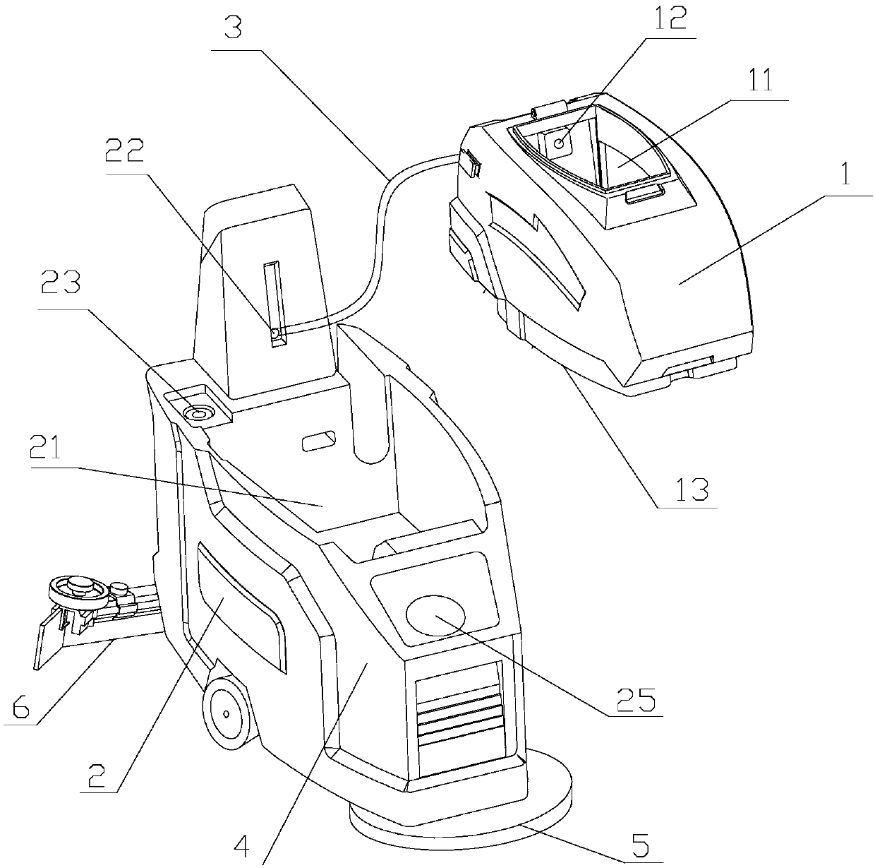
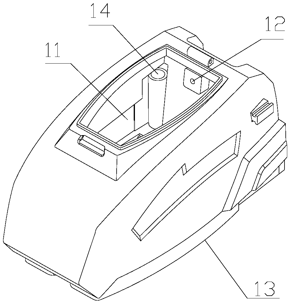
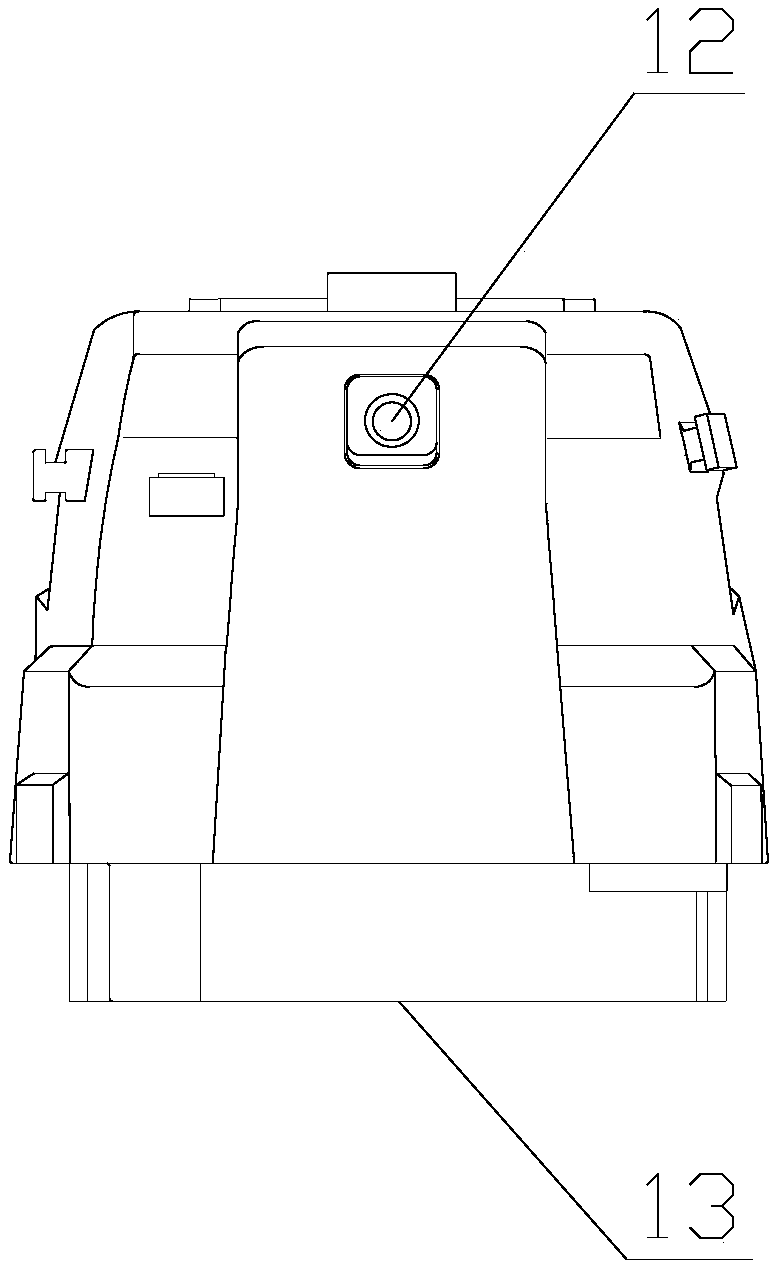
[0026] As shown in the drawings, a separate floor washing machine includes a sewage tank 1, a clean water tank 2, a suction motor, a sewage collection strip 6, and a sweeping plate 5 with several water outlets on the bottom surface. The sewage collection strip 6 passes through The sewage pipe is connected to the sewage tank 1; the sewage tank 1 is located above the clean water tank 2, and the sewage tank 1 is detachably connected to the clean water tank 2; the clean water tank 2 is provided with a clean water storage chamber 4 and a motor chamber 21; the motor chamber 21 is located inside the clean water tank 2, and the suction motor is located in the motor chamber 21; the inner wall of the motor chamber 21 and the outer wall of the clean water tank 2 form a sandwich structure, and the sandwich structure A clean water storage chamber 4 is formed; the sw...


PUM


Abstract

The invention discloses a separated floor scrubber, which comprises a sewage tank, a clean water tank, a air suction motor, a sewage collection strip and a sweeping plate. The sewage tank and the clean water tank are detachable, the bottom of the sweeping plate is provided with a plurality of water outlets, the sewage collection strip is connected with the sewage tank through a sewage pipe, and the sewage tank is positioned above the clean water tank and detachably connected with the clean water tank. The clean water tank is provided with a clean water storage chamber and a motor chamber, themotor chamber is positioned in a clean water tank body, and the suction motor is positioned in the motor chamber. The inner wall of the motor chamber and the outer wall of the clean water tank form aninterlayer structure which forms the clean water storage chamber, and the sweeping plate is communicated with the clean water storage chamber. The air suction motor can be protected from being wetted, and convenience in taking, fetching and maintenance of the air suction motor is achieved.

Description

technical field [0001] The invention relates to a floor washing machine, in particular to a separate type floor washing machine. Background technique [0002] The floor scrubber is a cleaning machine suitable for cleaning the hard bottom while absorbing the sewage and taking the sewage away from the site. It has the advantages of environmental protection, energy saving, and high efficiency. The floor washing machine usually consists of a sewage tank, a clean water tank, a sweeping disc, a suction motor, a brush motor and a sewage collection strip. The sewage tank is provided with a sewage inlet and an air suction port, the sewage inlet is connected with the sewage collection bar through the sewage pipe, and the air suction port is connected with the suction motor through the suction pipe; During the specific operation, clean water is injected into the water injection port of the clean water tank, and the clean water in the clean water tank flows out from the water outlet of...

Claims


Application Information

Patent Timeline
IPC IPC(8): A47L11/30A47L11/40
CPCA47L11/305A47L11/40A47L11/4016A47L11/4038
Inventor 李茂华温燕申月娇林鹭
Owner PANZHIHUA UNIV
Why Eureka
Try Eureka