High wear resistance stirring shaft

A stirring shaft, high wear-resistant technology, used in mixers with rotating stirring devices, dissolving, mixers and other directions, can solve the problems of poor stirring uniformity, short service life, easy to deform, etc., to prolong the service life, use Long service life and the effect of increasing service life

Inactive Publication Date: 2018-12-28
胡新军
View PDF4 Cites 1 Cited by
  • Summary
  • Abstract
  • Description
  • Claims
  • Application Information

AI Technical Summary

Problems solved by technology

[0003] At present, the stirring shaft in the stirrer has a good stirring effect, but its structure is single, the stirring uniformity is poor, and it is prone to deformation, resulting in short service life. Therefore, it is necessary to improve the stirring shaft

Method used


Image

  • High wear resistance stirring shaft
  • High wear resistance stirring shaft

Examples


Embodiment Construction

[0018] The following will clearly and completely describe the technical solutions in the embodiments of the present invention with reference to the accompanying drawings in the embodiments of the present invention. Obviously, the described embodiments are only some, not all, embodiments of the present invention. Based on the embodiments of the present invention, all other embodiments obtained by persons of ordinary skill in the art without making creative efforts belong to the protection scope of the present invention.

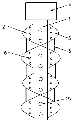
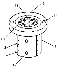
[0019] see Figure 1-2 , the present invention provides a technical solution: a high wear-resistant stirring shaft, including a shaft body 1, a shaft piece A2 and a shaft piece B3, the shaft piece A2 is spirally welded on the outer wall of the shaft body 1, and the shaft piece B3 is spirally welded It is welded on the outer wall of the shaft body 1, and the shaft piece A2 and the shaft piece B3 are symmetrically arranged, and the shaft piece A2 and the shaft p...


PUM


Abstract

The invention discloses a high wear resistance stirring shaft. The high wear resistance stirring shaft comprises a shaft body, a shaft sheet A and a shaft sheet B, the shaft sheet A is spirally weldedon the outer wall of the shaft body, the shaft sheet B is spirally welded on the outer wall of the shaft body, the shaft sheet A and the shaft sheet B are symmetrically arranged and are welded together in a staggering way, a shaft sleeve is installed at the upper end of the shaft body, the shaft sheet A and the shaft sheet B are fixedly connected through a reinforcing rib, and a plurality of through holes are evenly distributed in the outer walls of the shaft sheet A and the shaft sheet B. The structural design is novel, the structure stability is good, the stirring shaft has an excellent stirring performance, the symmetrical spiral shaft sheets are adopted to improve the stirring uniformity of the material, and in addition, the stirring shaft has an excellent wear resistance property, and has long service life.

Description

technical field [0001] The invention relates to the technical field of stirring shafts, in particular to a highly wear-resistant stirring shaft. Background technique [0002] In the agitator, in order to make the various mixtures being stirred can be mixed quickly and evenly, the stirring shaft needs to be able to produce a strong turbulence effect, so that various mixtures undergo large irregular movements, thereby accelerating the stirring effect. [0003] At present, the stirring shaft in the stirrer has a good stirring effect, but its structure is single, the stirring uniformity is poor, and it is prone to deformation, resulting in short service life. Therefore, it is necessary to improve the stirring shaft. Contents of the invention [0004] The purpose of the present invention is to provide a highly wear-resistant stirring shaft to solve the problems raised in the above-mentioned background technology. [0005] In order to achieve the above object, the present inven...

Claims


Application Information

Patent Timeline
Patent Type & Authority Applications(China)
IPC IPC(8): B01F7/00
CPCB01F27/0531B01F27/1141B01F27/212B01F27/213B01F27/191
Inventor 薛慧敏胡新军梁晶晶
Owner 胡新军
Why Eureka
Try Eureka