
A continuous cutting device for transmission chain

A technology of cutting device and transmission chain, applied in the direction of feeding device, positioning device, storage device, etc., can solve the problems of low work efficiency, manual measurement error, high manual labor intensity, etc., to meet the requirements of mass processing and production, guarantee measurement The effect of cutting accuracy and low labor intensity

Active Publication Date: 2019-11-12
安徽省绩溪县飞奔链传动有限公司
View PDF5 Cites 0 Cited by
  • Summary
  • Abstract
  • Description
  • Claims
  • Application Information

AI Technical Summary

Problems solved by technology

[0002] In the production process of the transmission chain, the longer chain is generally manufactured first, and then the longer chain is cut off according to the needs to form several products with uniform length; For sprocket transmission, if the traditional horizontal measurement and cutting mechanism is used, there will be certain errors in the transmission after the chain is cut, and this method is usually not used. Most of the cutting process is manually measured and then cut on the punching machine. Its manual labor intensity is high, time-consuming and labor-intensive. At the same time, there will be certain errors in manual measurement. It takes a period of time between each measurement and cutting and the placement of the chain. The work efficiency is low and the operation is cumbersome. Therefore, there is an urgent need for a Measuring and cutting structure directly after chain production and processing

Method used


Image

  • A continuous cutting device for transmission chain

Examples


Embodiment Construction

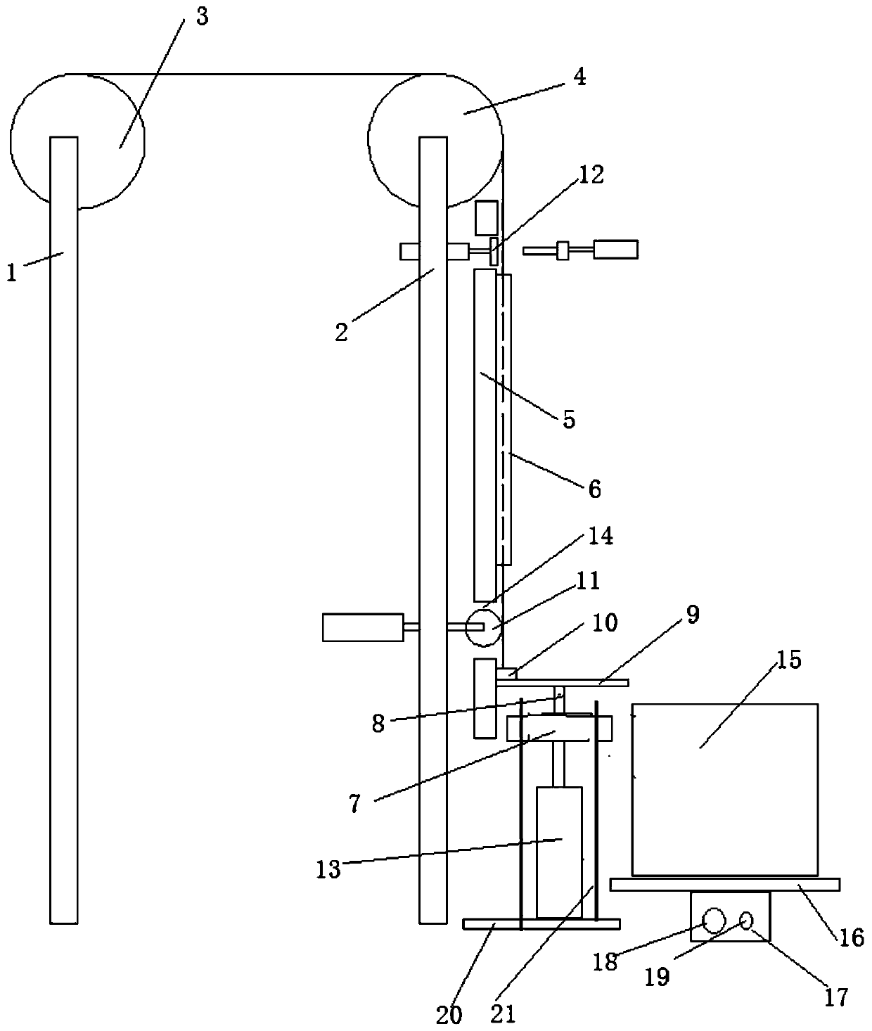
[0015] See attached picture.

[0016] A continuous cutting device for a transmission chain, comprising two brackets 1 and 2 arranged at intervals, on which a driving sprocket 3 and a driven sprocket 4 for driving the transmission chain are respectively mounted on the brackets 1 and 2, characterized in that: A material guide worktable 5 is arranged vertically below the discharge end of the driven sprocket 4. The material guide worktable 5 is provided with a guide plate 6 corresponding to the vertical discharge direction of the driven sprocket 4, so The upper end of the guide workbench 5 is provided with a cutting mechanism corresponding to its guide plate, and the outer side of the lower end of the guide plate 6 is provided with a measuring and receiving mechanism that cooperates with it. The measuring and receiving mechanism includes a liftable The movable seat 7, on which a limit plate 9 is installed through a support rod 8, a contactor 10 is provided on the limit plate 9 corres...


PUM


Abstract

The invention discloses a transmission chain continuous type cutoff device. The transmission chain continuous type cutoff device comprises two supports arranged in a spaced mode. A driving chain wheeland a driven chain wheel for driving a transmission chain to run are erected on the supports separately. A guide workbench is vertically arranged below the discharging end of the driven chain wheel and provided with a guide plate corresponding to the driven chain wheel in the direction perpendicular to the discharging direction. A cutoff mechanism is arranged at the upper end of the guide workbench. A measurement and receiving mechanism is arranged on the outer side of the lower end of the guide plate and matched with the guide plate. The measurement and receiving mechanism comprises a movingbase capable of ascending and descending. A limiting plate is installed on the moving base through a supporting rod, and a contactor is arranged at the position, corresponding to the guide plate, ofthe limiting plate. A movable transitional wheel is installed at the position, above the moving base, of the limiting plate. A receiving frame capable of moving horizontally is arranged below the moving base. According to the transmission chain continuous type cutoff device, the manual labor intensity is low, and time and labor are saved; and by adoption of continuous operation, the operating efficiency is improved, the measurement and discharging precision of materials cut off is ensured, and the requirements of large-batch processing and production are met.

Description

Technical field: [0001] The invention relates to the field of transmission chain production and processing, and mainly relates to a continuous cutting device for a transmission chain. Background technique: [0002] In the transmission chain production process, generally a longer chain is manufactured first, and then the longer chain is cut as needed to form a number of products of uniform length; the entire chain is processed before returning to operation, because most of the chains are passed If the sprocket is driven by a traditional horizontal measuring and cutting mechanism, there will be a certain error in its transmission after the chain is cut. This method is usually not used. Most of the cutting process is manually measured and then cut on a punch. The manual labor is intensive, time-consuming and labor-intensive. At the same time, there will be certain errors in manual measurement. It takes a period of time between each measurement and cutting and the placement of the ch...

Claims


Application Information

Patent Timeline
Patent Type & Authority Patents(China)
IPC IPC(8): B21L9/02B21D28/02B21D43/20B21D43/08
CPCB21D28/02B21D43/08B21D43/20B21L9/02
Inventor 巫新锋
Owner 安徽省绩溪县飞奔链传动有限公司
Learn More