
Optical cement bonding method and device

A technology of laminating device and optical glue, applied in chemical instruments and methods, lamination devices, layered products, etc., can solve the problems of optical glue overflowing and bubble rebound, and reduce glue overflow, reduce continuous extrusion, The effect of improving product yield and efficiency

Inactive Publication Date: 2018-12-28
TRULY OPTO ELECTRONICS
View PDF0 Cites 1 Cited by
  • Summary
  • Abstract
  • Description
  • Claims
  • Application Information

AI Technical Summary

Problems solved by technology

The current optical adhesive bonding method is generally to place the optical adhesive on the substrate to be bonded, and then use a roller to press down from the edge of one end of the optical adhesive, and then roll it to the other side, and because the optical adhesive is getting thinner and softer , and since most of the substrates to be bonded are narrow-frame products, such a bonding method often causes the optical glue to overflow when the pressure of the roller is bonded, resulting in the risk of bubble rebound

Method used


Image

  • Optical cement bonding method and device
  • Optical cement bonding method and device
  • Optical cement bonding method and device

Examples


Embodiment 1

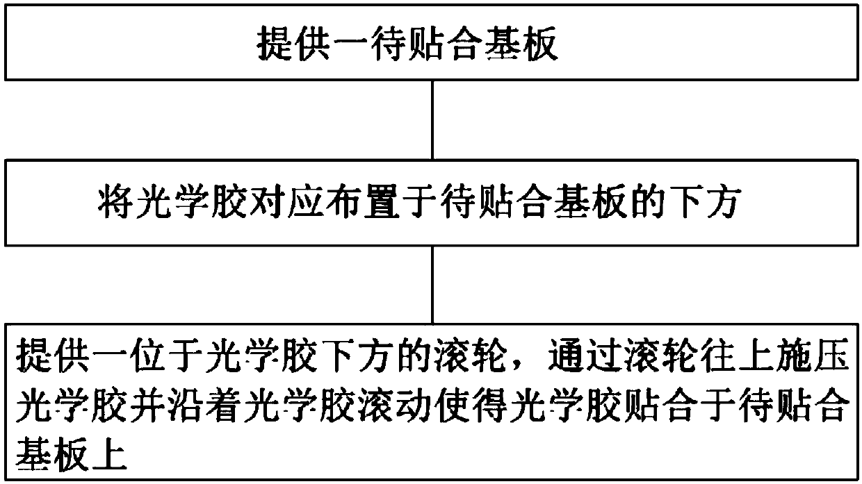
[0025] Such as figure 1 As shown, this embodiment provides an optical adhesive bonding method. The optical glue bonding method includes the following steps:

[0026] Provide a substrate to be bonded; arrange the optical glue correspondingly below the substrate to be bonded; provide a roller located under the optical glue, press the optical glue upward through the roller and roll along the optical glue so that the optical glue is bonded to the substrate to be bonded Attached to the substrate.

[0027] The optical glue laminating method provided by the present invention can effectively avoid the glue overflow problem caused by downward pressure lamination in the prior art by using the roller to apply upward pressure to laminate the optical glue on the substrate to be bonded, and effectively reduce the There is a risk of bubble rebound, improve product yield and efficiency, and improve product quality. specifically. In this embodiment, the rolling path of the roller along the...

Embodiment 2

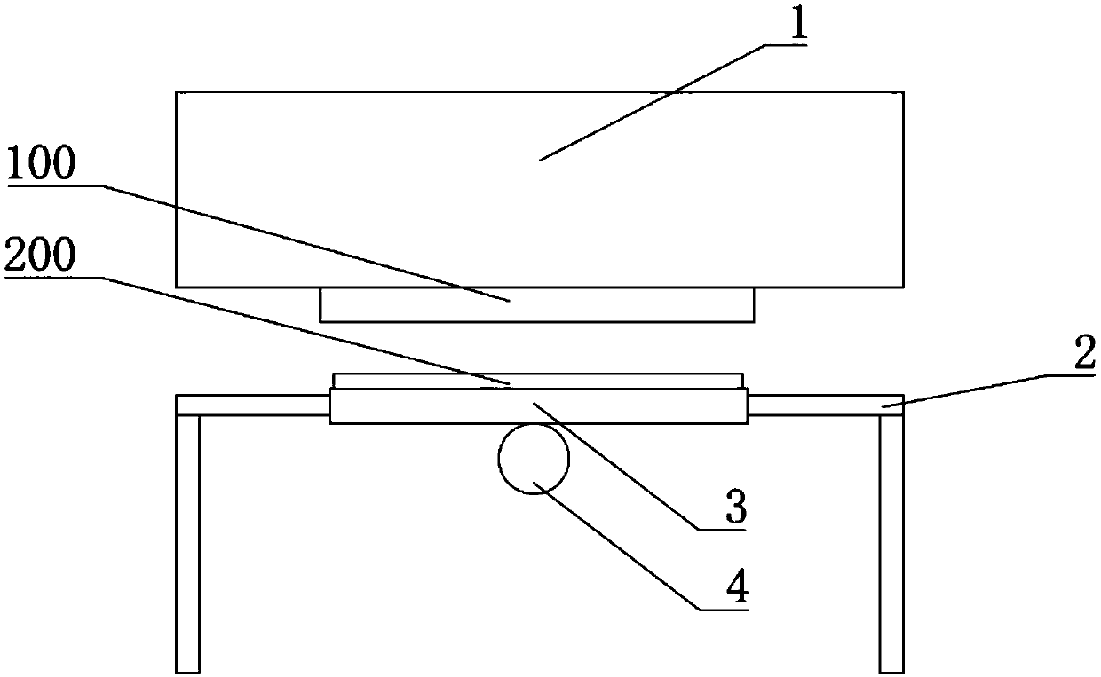
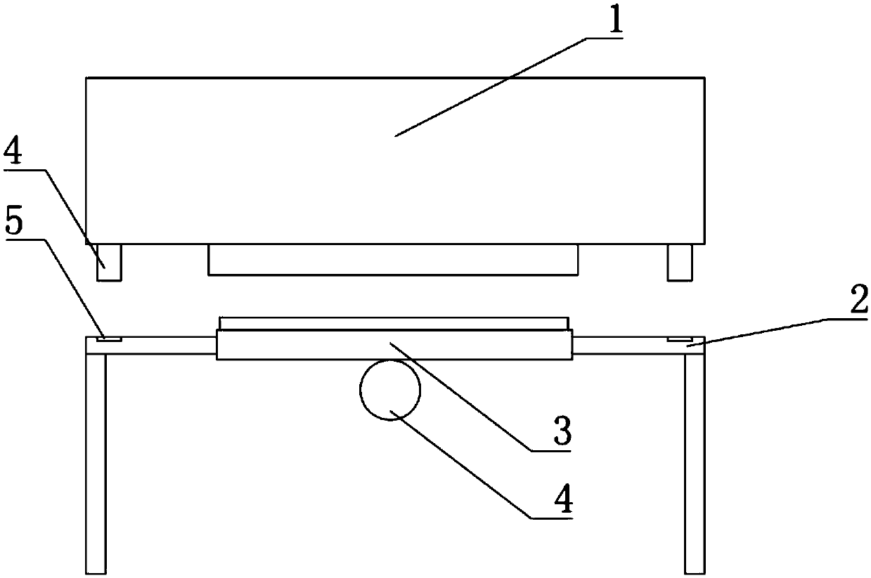
[0031] Such as figure 2 As shown, this embodiment provides an optical glue bonding device for realizing the optical glue bonding method described in the above embodiment, the optical glue bonding device includes a substrate fixing part 1 to be bonded, arranged on the The machine platform 2 below the substrate fixing part 1 to be bonded, the screen plate 3 and the roller 4 which are arranged on the machine platform 2 and correspond to the substrate fixing part 1 to be bonded; the substrate fixing part 1 to be bonded is used for The substrate 100 to be bonded is fixed by vacuum suction, the screen 3 is used to fix the optical glue 200 toward the side of the substrate fixing part 1 to be bonded, and the roller 4 is arranged on the screen 3 facing away from the substrate to be bonded. Substrate fixing part 1 side.

[0032] In this way, the optical adhesive 200 bonding device provided in this embodiment can utilize the substrate fixing part 1 to be bonded by setting the substrate...


PUM


Abstract

The invention provides an optical cement bonding method and device. The method comprises following steps: a to-be-bonded substrate is provided; optical cement is distributed in the position below theto-be-bonded substrate correspondingly; a roller located below the optical cement is provided, and the roller applies pressure upward to the optical cement and rolls along the optical cement, so thatthe optical cement is enabled to be attached to the to-be-bonded substrate. The device comprises a to-be-bonded substrate fixing part, a machine table arranged below the to-be-bonded substrate fixingpart, a mesh plate arranged on the machine table and corresponding to the to-be-bonded substrate fixing part and the roller, wherein the to-be-bonded substrate fixing part is used for fixing the to-be-bonded substrate by vacuum absorption, the optical cement is fixed on one side, facing the to-be-bonded substrate fixing part, of the mesh plate, and the roller is arranged on one side, opposite to the to-be-bonded substrate fixing part, of the mesh plate. According to the optical cement bonding method and device, the problem of cement overflow during bonding of the optical cement can be solved effectively.

Description

technical field [0001] The invention relates to the field of display technology, in particular to an optical adhesive bonding method and device. Background technique [0002] Nowadays, as people have higher and higher requirements for the user experience of display products, they also have higher and higher requirements for thinner and lighter products and narrower borders. Products such as mobile phones, tablet computers and monitors are getting thinner and thinner. The optical glue in the product is also required to be thinner and thinner, and in order to fill the surface level difference of various substrates to be bonded, such as the ink level difference on the cover plate caused by ink coating, the optical glue is also getting softer. The current optical adhesive bonding method is generally to place the optical adhesive on the substrate to be bonded, and then use a roller to press down from the edge of one end of the optical adhesive, and then roll it to the other side,...

Claims


Application Information

Patent Timeline
Patent Type & Authority Applications(China)
IPC IPC(8): B32B37/10B32B37/00B32B37/12
CPCB32B37/1045B32B37/003B32B37/12
Inventor 余立富吴德生
Owner TRULY OPTO ELECTRONICS
Learn More