Energy-absorbing beam, cab chassis structure of rail vehicle and rail vehicle

A rail vehicle and driver's cab technology, applied in the field of driver's cab underframe structure and rail vehicles, can solve problems such as warping deformation, car climbing, no energy absorption function, etc., achieve good stability performance, improve anti-collision energy absorption Function, anti-climbing effect

Active Publication Date: 2020-04-28
CRRC TANGSHAN CO LTD +1
View PDF6 Cites 0 Cited by
  • Summary
  • Abstract
  • Description
  • Claims
  • Application Information

AI Technical Summary

Problems solved by technology

[0004] When the collision occurs, the anti-climbing device has completed the energy absorption function, but if the collision process is still in progress, the cab structure will be further compressed, but the cab underframe structure in the prior art only has a load-bearing function, and itself does not have energy absorption Function, the deformation of the underframe structure is uncontrollable, which will cause the underframe structure to warp upward or downward under the impact force, and there is still the risk of climbing, which will endanger the life safety of the driver

Method used


Image

  • Energy-absorbing beam, cab chassis structure of rail vehicle and rail vehicle
  • Energy-absorbing beam, cab chassis structure of rail vehicle and rail vehicle
  • Energy-absorbing beam, cab chassis structure of rail vehicle and rail vehicle

Examples


Embodiment 1

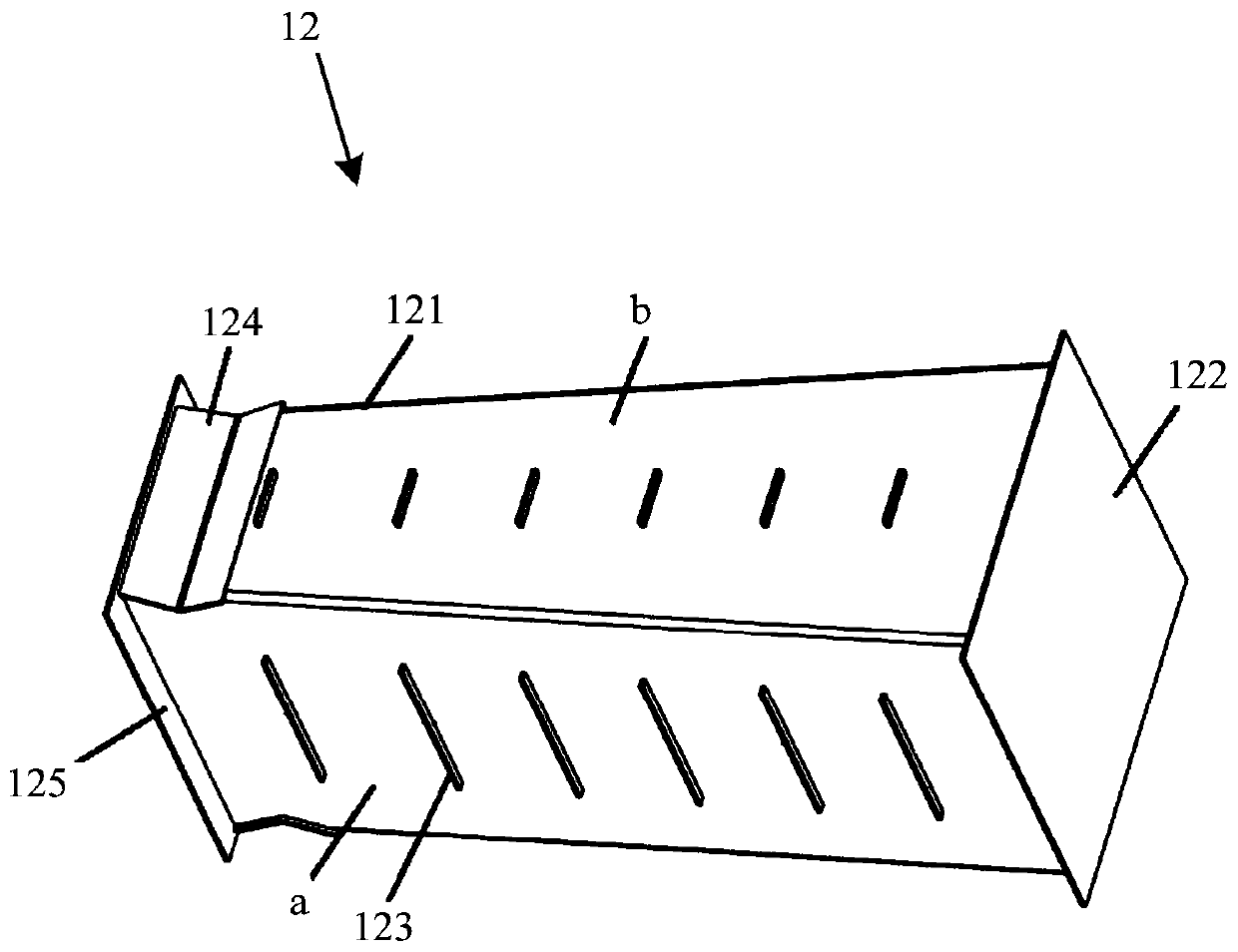
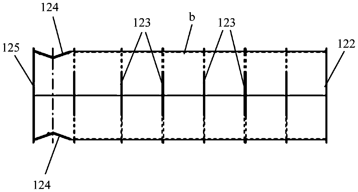
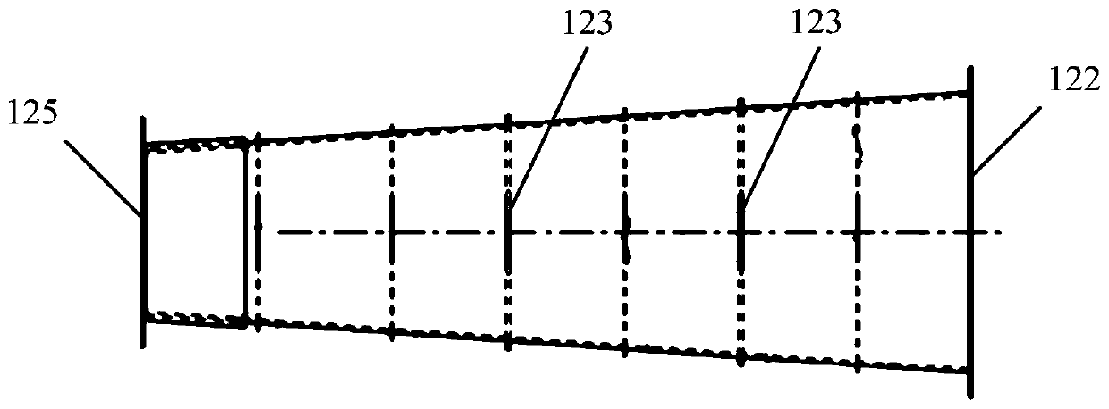
[0065] figure 1 It is a front view of an energy-absorbing beam provided by an embodiment of the present invention. figure 2 Side section of an energy-absorbing beam provided for an embodiment of the present invention Figure 1 . image 3 Side section of an energy-absorbing beam provided for an embodiment of the present invention Figure II . Figure 4 A schematic structural diagram of an energy-absorbing beam provided by an embodiment of the present invention. Figure 5 It is a structural schematic diagram of an underframe structure of a driver's cab of a rail vehicle provided by an embodiment of the present invention. refer to Figure 1 to Figure 5 As shown, the present embodiment provides an energy-absorbing beam. The energy-absorbing beam 12 can be applied to the driver's cab of a rail vehicle. In actual implementation, the energy-absorbing beam 12 can be connected to the chassis structure 1 of the driver's cab.

[0066] By arranging the energy-absorbing beam 12 on t...

Embodiment 2

[0077] Figure 5 It is a structural schematic diagram of an underframe structure of a driver's cab of a rail vehicle provided by an embodiment of the present invention. Image 6 It is a structural schematic diagram of a driver's cab of a rail vehicle provided by an embodiment of the present invention. refer to Figure 1 to Figure 6 As shown, the present embodiment provides an underframe structure for a driver's cab of a rail vehicle.

[0078] The underframe structure 1 includes: two symmetrically arranged side beams 14, an underframe backboard 11 connected between the rear ends of the two side beams 14 and a front end connected between the two side beams 14. front end plate 110 . That is to say, the chassis back panel 11 is located at the rear side of the chassis structure 1 , the front panel 110 is located at the front side of the chassis structure 1 , and the two side beams 14 are respectively located at two sides of the chassis structure 1 . Wherein, the front end face ...

Embodiment 3

[0092] Image 6 It is a structural schematic diagram of a driver's cab of a rail vehicle provided by an embodiment of the present invention. refer to Figure 1 to Figure 6 As shown, this embodiment provides a rail vehicle, which includes a car body and a driver's cab, wherein the driver's cab is connected to one end of the car body.

[0093] The driver's cab includes: a skeleton structure 2 and an underframe structure 1 welded at the bottom of the skeleton structure 2 .

[0094] Wherein, the underframe structure 1 has the same structure as the underframe structure provided in the second embodiment, and can bring about the same or similar technical effects, so it will not be described here one by one, and details can be referred to the descriptions of the first and second embodiments .

[0095] Wherein, the frame structure 2 specifically includes: a frame back plate 21 welded on the chassis back plate 11, two symmetrically arranged window side vertical beams 24, a window low...


PUM


Abstract

The invention provides an energy-absorbing beam, a cab chassis structure of a rail vehicle and a rail vehicle. The energy-absorbing beam is connected with the cab chassis structure of the rail vehicle. The energy-absorbing beam comprises a cylindrical shell and at least one partition plate located inside the shell. The cross-sectional area of the housing gradually decreases in the direction from the rear end of the cab to the front end of the cab; The partition plate is connected with the inner wall of the shell, and the plane direction of the partition plate is mutually perpendicular to the traveling direction of the rail vehicle; A V-shaped notch is formed on the outer wall of a part of the outer shell facing the front of the rail vehicle, and a corner plate matching the shape of the V-shaped notch is welded on the V-shaped notch, thereby improving the collision-proof and energy-absorbing function of the cab chassis structure.

Description

technical field [0001] The invention relates to the technical field of rail vehicles, in particular to an energy-absorbing beam, an underframe structure of a driver's cab of a rail vehicle and the rail vehicle. Background technique [0002] There are many types of rail vehicles, mainly including: underground subway trains, express rail and light rail trains connecting the city center and suburbs, and trams that shuttle through the bustling areas of the city. [0003] The anti-collision passive safety design of rail vehicles is an important guarantee for the safe operation of vehicles. The rail vehicle includes a car body and a driver's cab connected to one end of the car body. The driver's cab includes an underframe structure and a skeleton structure connected to the underframe structure. In order to prevent the vehicle from climbing, the prior art installs an anti-climbing Device, specifically, the anti-climbing device is installed on the front wall of the driver's cab, th...

Claims


Application Information

Patent Timeline
Patent Type & Authority Patents(China)
IPC IPC(8): B61F19/04B61D17/04
CPCB61D17/04B61F19/04Y02T30/00
Inventor 刘晋罗超王卉子鞠美娜伊召锋栾小东高峰张相宁
Owner CRRC TANGSHAN CO LTD
Why Eureka
Try Eureka