Energy absorbing beam, cab underframe structure of rail vehicle and rail vehicle
A rail vehicle and energy-absorbing beam technology, applied in the field of rail vehicles, can solve the problems of car climbing, warping deformation, no energy-absorbing function, etc., to improve the anti-collision energy-absorbing function, good stability, and prevent car climbing. Effect
- Summary
- Abstract
- Description
- Claims
- Application Information
AI Technical Summary
Problems solved by technology
Method used
Image
Examples
Embodiment 1
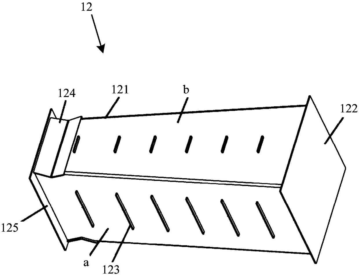
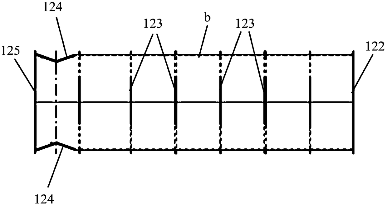
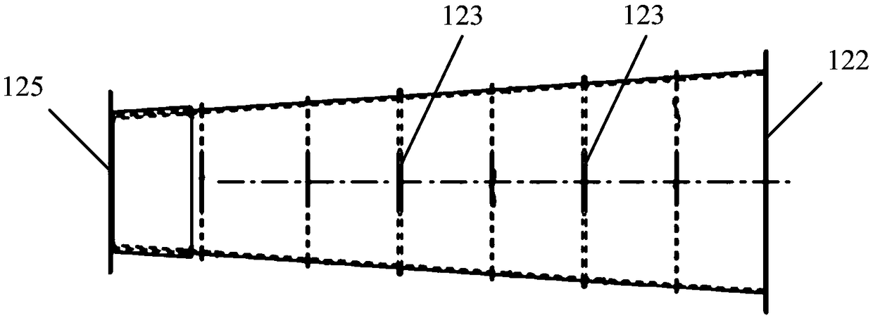
[0065] figure 1 It is a front view of an energy-absorbing beam provided by an embodiment of the present invention. figure 2 Side section of an energy-absorbing beam provided for an embodiment of the present invention Figure 1 . image 3 Side section of an energy-absorbing beam provided for an embodiment of the present invention Figure II . Figure 4 A schematic structural diagram of an energy-absorbing beam provided by an embodiment of the present invention. Figure 5 It is a structural schematic diagram of an underframe structure of a driver's cab of a rail vehicle provided by an embodiment of the present invention. refer to Figure 1 to Figure 5 As shown, the present embodiment provides an energy-absorbing beam. The energy-absorbing beam 12 can be applied to the driver's cab of a rail vehicle. In actual implementation, the energy-absorbing beam 12 can be connected to the chassis structure 1 of the driver's cab.
[0066] By arranging the energy-absorbing beam 12 on t...
Embodiment 2
[0077] Figure 5 It is a structural schematic diagram of an underframe structure of a driver's cab of a rail vehicle provided by an embodiment of the present invention. Figure 6 It is a structural schematic diagram of a driver's cab of a rail vehicle provided by an embodiment of the present invention. refer to Figure 1 to Figure 6 As shown, the present embodiment provides an underframe structure for a driver's cab of a rail vehicle.
[0078] The underframe structure 1 includes: two symmetrically arranged side beams 14, an underframe backboard 11 connected between the rear ends of the two side beams 14 and a front end connected between the two side beams 14. front end plate 110 . That is to say, the chassis back panel 11 is located at the rear side of the chassis structure 1 , the front panel 110 is located at the front side of the chassis structure 1 , and the two side beams 14 are respectively located at two sides of the chassis structure 1 . Wherein, the front end face...
Embodiment 3
[0092] Figure 6 It is a structural schematic diagram of a driver's cab of a rail vehicle provided by an embodiment of the present invention. refer to Figure 1 to Figure 6 As shown, this embodiment provides a rail vehicle, which includes a car body and a driver's cab, wherein the driver's cab is connected to one end of the car body.
[0093] The driver's cab includes: a skeleton structure 2 and an underframe structure 1 welded at the bottom of the skeleton structure 2 .
[0094] Wherein, the underframe structure 1 has the same structure as the underframe structure provided in the second embodiment, and can bring about the same or similar technical effects, so it will not be described here one by one, and details can be referred to the descriptions of the first and second embodiments .
[0095] Wherein, the frame structure 2 specifically includes: a frame back plate 21 welded on the chassis back plate 11, two symmetrically arranged window side vertical beams 24, a window lo...
PUM
| Property | Measurement | Unit |
|---|---|---|
| Angle range | aaaaa | aaaaa |
Abstract
Description
Claims
Application Information
 - R&D
- Intellectual Property
- Life Sciences
- Materials
- Tech Scout
- Unparalleled Data Quality
- Higher Quality Content
- 60% Fewer Hallucinations
Browse by: Latest US Patents, China's latest patents, Technical Efficacy Thesaurus, Application Domain, Technology Topic, Popular Technical Reports.
© 2025 PatSnap. All rights reserved.Legal|Privacy policy|Modern Slavery Act Transparency Statement|Sitemap|About US| Contact US: help@patsnap.com


