Conveyor belt tensioning device

A technology of tensioning mechanism and conveyor belt, which is applied in the field of agricultural machinery, can solve the problems of unsightly exposure of the adjustment mechanism, affect the quality of conveying, and inconvenient adjustment, etc., and achieve consistent tension, not easy to deviate, and good force consistency Effect

Pending Publication Date: 2018-12-28
NANJING AGRI MECHANIZATION INST MIN OF AGRI
View PDF0 Cites 0 Cited by
  • Summary
  • Abstract
  • Description
  • Claims
  • Application Information

AI Technical Summary

Problems solved by technology

There are problems such as inconvenient adjustment, inability to self-adaptively adjust according to the set tension force, and the exposed adjustment mechanism is not beautiful, and the exposed tension adjustment mechanism of the conveyor belt of the windrower also causes problems such as hanging grass and affecting the conveying quality

Method used


Image

  • Conveyor belt tensioning device
  • Conveyor belt tensioning device
  • Conveyor belt tensioning device

Examples


Embodiment 1

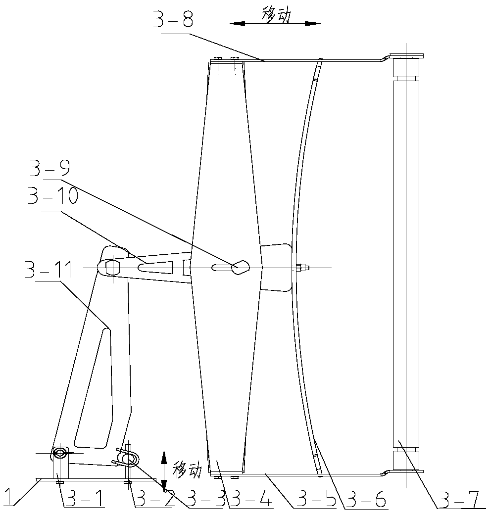
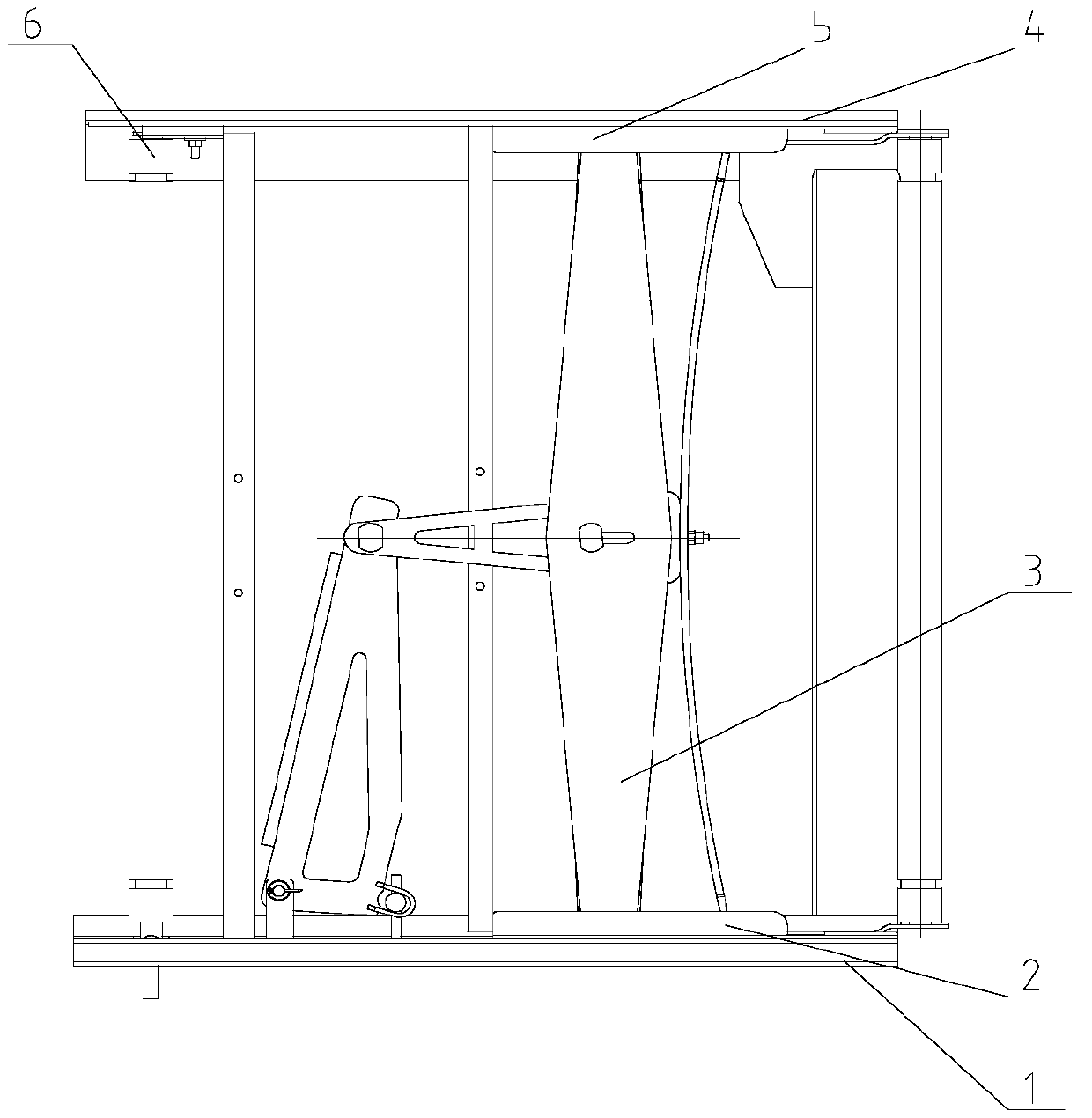
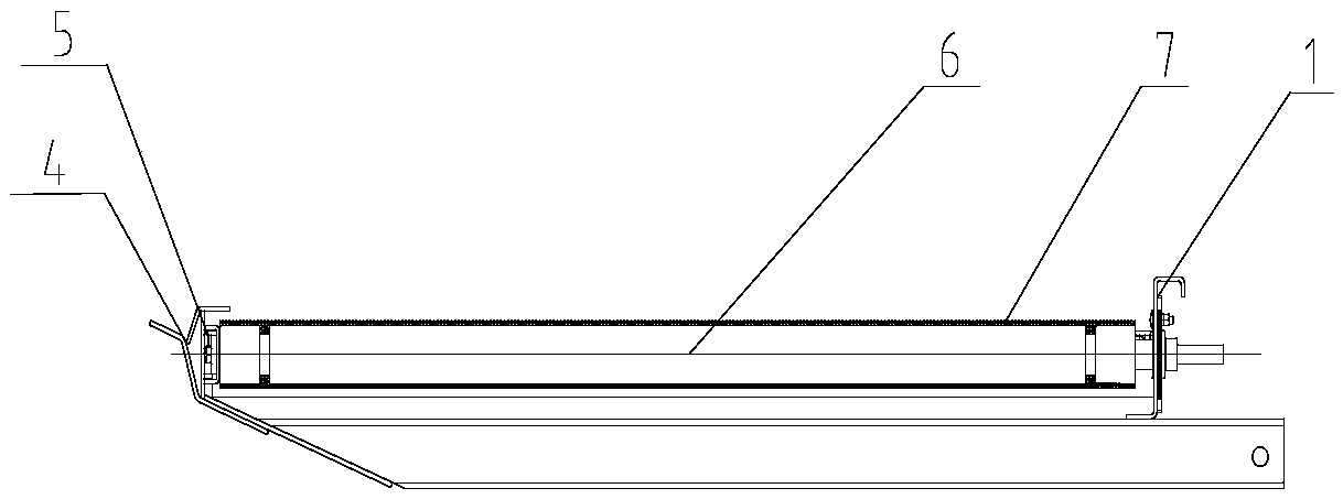
[0020] The present invention is a conveyor belt tensioning mechanism with simple structure and low cost, which can self-adaptively adjust the tension force of the tensioning mechanism, see Figure 1-4 , including a first frame 4 and a second frame 1 arranged in parallel, a circle of conveyor belt 7 surrounds the first frame and the second frame, and a first guide groove 5 is provided on the opposite inner side of the first frame 4 and the second frame 1 and the second guide groove 2, the conveyor belt driving shaft 6 is fixed between the first frame 4 and the second frame 1, and the first side bracket plates 3-8 are slidingly arranged in the first guide groove 5 and the second guide groove 2 respectively. and the second side support plate 3-5, between the first side support plate 3-8 and the second side support plate 3-8, the conveyor belt driven shaft 3-7 is fixed at the end away from the conveyor belt driving shaft 6, An elastic tensioning mechanism 3 for adjusting the tensi...

Embodiment 2

[0023] For this example see Figure 5 , the difference from Example 1 is that in Example 1, the elastic steel plate is replaced by a rigid steel plate 3-12, and the adjusting end is fixed with a linear motor 3-14 through a fixing seat, and the linear motor 3-14 is connected to the conveyor through a controller. With a pressure sensor 3-13 on the driven shaft 3-7. The pressure sensor 3-13 is fixed on the supporting shaft of the driven shaft to obtain the pressure of the driven shaft on the driven shaft by the conveyor belt in real time.

[0024] When the pressure sensor 3-13 detects that the pressure of the driven shaft is less than the tension range required for the tension of the conveyor belt, the linear motor 3-14 adjusts the length of the threaded pull rod 3-2, pulls the adjustment end to change the swing arm angle, and drives The driven shaft moves in the guide groove, thereby changing the tension.

[0025] When the pressure sensor detects that the pressure on the drive...


PUM


Abstract

A conveyor belt tensioning device comprises a first frame (4) and a second frame (1) arranged in parallel, A first guide groove (5) and a second guide groove (2) are respectively arranged on oppositeinner sides of the first frame (4) and the second frame (1), the device is characterized in that a conveyor belt driving shaft (6) is fixed between the first frame (4) and the second frame (1), and afirst side support plate (3-8) and a second side support plate (3-5) are respectively slidably arranged in the first guide groove (5) and the second guide groove (2). One ends of the first side support plate (3-8) and the second side support plate (3-8) are fixed with a conveyor belt driven shaft (3-7) far away from the conveyor belt driving shaft (6), an elastic tensioning mechanism (3) which adjusts tension of the conveyer belt is arranged between the conveyor belt driving shaft (6) and the conveyor belt driven shaft (3-7), and the elastic tensioning mechanism (3) can adjust the distance between the conveyor belt driving shaft and the conveyor belt driven shaft. The invention has the advantages of simple structure, strong operability, quick and convenient adjustment of the tensioning degree of the tensioning mechanism and difficulty in grass hanging.

Description

technical field [0001] The invention relates to a conveyor belt tensioning device, which belongs to the technical field of agricultural machinery. Background technique [0002] The conveyor belt tensioning mechanism is an important part of the conveyor belt conveyor device such as rape windrower and picker, which is used to tension the conveyor belt and prevent the conveyor belt from slipping. At present, the windrower conveyor belt is generally a rubber cloth webbing belt. Due to the harsh working environment, there is a common problem of large deformation of the conveyor belt. During work, it is necessary to frequently adjust the tension of the conveyor belt to prevent slipping and deviation from affecting the conveying effect. At present, The tensioning mechanism of the conveyor belt is generally provided with spring pull rods at both ends of the driven shaft of the conveyor belt, and the tension of the conveyor belt can be adjusted by adjusting the length of the pull rod...

Claims


Application Information

Patent Timeline
IPC IPC(8): B65G23/44
CPCB65G23/44
Inventor 张敏吴崇友王刚汤庆吴俊沐森林
Owner NANJING AGRI MECHANIZATION INST MIN OF AGRI
Why Eureka
Try Eureka