Collision structure and robot of a kind of robot

A robot and pressure sensor technology, applied in the field of robots, can solve the problems of large collision resistance, uneven force, poor collision induction feedback effect, etc., and achieve the effect of high adaptability

Active Publication Date: 2021-07-27
广东寻夏科技有限公司
View PDF6 Cites 0 Cited by
  • Summary
  • Abstract
  • Description
  • Claims
  • Application Information

AI Technical Summary

Problems solved by technology

[0002] The robot's collision structure system is widely used in various walking robots, such as sweeping robots, food delivery robots and factory transportation robots. At present, in the collision structure system of robots, shrapnel or pendulum are basically used In the way of rods, the traditional pendulum uses the contact method between the hypotenuse and the surface, which makes the collision resistance larger, and the collision induction of the sweeping robot is not sensitive, resulting in poor collision induction and feedback effects. When the side collision of the collision part is under force, it is easy to cause poor impact sensor feedback effect, and there is a certain requirement for the collision angle. It is suitable for smaller structures or structures with multiple collision sensors.

Method used


Image

  • Collision structure and robot of a kind of robot
  • Collision structure and robot of a kind of robot
  • Collision structure and robot of a kind of robot

Examples


Embodiment 1

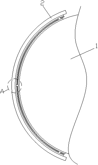
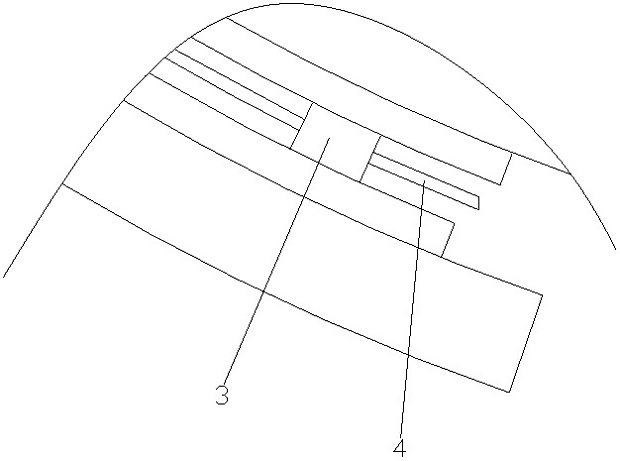
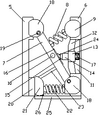
[0029] Such as Figure 1-4 As shown, a collision structure of a robot includes a mounting part 1 and a collision part 2, a buffer device 3 is arranged between the installation part 1 and the collision part 2, and more than one buffer device 3 is provided, and the buffer device 3 is provided with a satellite shaft 4 and the adjacent buffer device 3 is connected through the satellite shaft 4. The buffer device 3 includes a satellite board 5 and a mounting board 6, and the satellite board 5 is fixedly connected with the collision part 2. The mounting plate 6 is fixedly connected to the mounting portion 1, and a connecting rod 7 is arranged between the satellite plate 5 and the mounting plate 6, and the two ends of the connecting rod 7 are respectively connected to the mounting plate 6 and the satellite plate 5 in rotation and arranged obliquely. The connecting rod 7 is provided with a first buffer spring 8, one end of the first buffer spring 8 is perpendicular to the connecting r...

Embodiment 2

[0032] Such as Figure 1-4As shown, a collision structure of a robot includes a mounting part 1 and a collision part 2, a buffer device 3 is arranged between the installation part 1 and the collision part 2, and more than one buffer device 3 is provided, and the buffer device 3 is provided with a satellite shaft 4 and the adjacent buffer device 3 is connected through the satellite shaft 4. The buffer device 3 includes a satellite board 5 and a mounting board 6, and the satellite board 5 is fixedly connected with the collision part 2. The mounting plate 6 is fixedly connected to the mounting portion 1, and a connecting rod 7 is arranged between the satellite plate 5 and the mounting plate 6, and the two ends of the connecting rod 7 are respectively connected to the mounting plate 6 and the satellite plate 5 in rotation and arranged obliquely. The connecting rod 7 is provided with a first buffer spring 8, one end of the first buffer spring 8 is perpendicular to the connecting ro...


PUM


Abstract

The invention discloses a collision structure of a robot and the robot. The collision structure of the robot includes a mounting part and a collision part. A buffer device is arranged between the installation part and the collision part. More than one buffer device is provided. The buffer device A satellite shaft is arranged between them and adjacent buffer devices are connected by a satellite shaft. The buffer device includes a satellite board and a mounting board, and a connecting rod is arranged between the satellite board and the mounting board, and the two ends of the connecting rod are respectively It is rotatably connected with the mounting plate and the satellite plate and arranged obliquely. The connecting rod is provided with a first buffer spring. One end of the first buffer spring is perpendicular to the connecting rod and is fixedly connected. The other end of the first buffer spring is arranged There are first buffer rubber particles, the first buffer rubber particles are fixedly connected to the mounting plate, the connecting rod is provided with a connecting hole matched with the satellite shaft, and the satellite shaft is inserted into the connecting hole; the collision structure of the robot Good feedback on collisions.

Description

technical field [0001] The invention relates to the field of robots, in particular to a collision structure of a robot and the robot. Background technique [0002] The robot's collision structure system is widely used in various walking robots, such as sweeping robots, food delivery robots and factory transportation robots. At present, in the collision structure system of robots, shrapnel or pendulum are basically used In the way of rods, the traditional pendulum uses the contact method between the hypotenuse and the surface, which makes the collision resistance larger, and the collision induction of the sweeping robot is not sensitive, resulting in poor collision induction and feedback effects. When the side collision of the collision part is under force, it is easy to cause poor impact sensor feedback, and there is a certain requirement for the collision angle, which is suitable for smaller structures or structures with multiple collision sensors. [0003] In view of this...

Claims


Application Information

Patent Timeline
Patent Type & Authority Patents(China)
IPC IPC(8): B25J19/00
CPCB25J19/00B25J19/0091
Inventor 黄国静许东伟
Owner 广东寻夏科技有限公司
Why Eureka
Try Eureka