Device for automatically calibrating clamp rigidity and application method thereof

An automatic calibration and stiffness technology, applied in the mechanical field, can solve the problems affecting the calibration accuracy of clamps, the force-displacement curve is not smooth enough, the loading force and displacement fluctuations, etc., and achieve the effect of smooth and continuous stiffness test process and accurate stiffness measurement

Active Publication Date: 2018-12-28
DALIAN UNIV OF TECH
View PDF8 Cites 14 Cited by
  • Summary
  • Abstract
  • Description
  • Claims
  • Application Information

AI Technical Summary

Problems solved by technology

[0004] The loading process of the existing clamp calibration device often adopts thread loading, which is prone to crawling phenomenon during the loading process, and the loading force and displacement produce large fluctuati...

Method used


Image

  • Device for automatically calibrating clamp rigidity and application method thereof
  • Device for automatically calibrating clamp rigidity and application method thereof
  • Device for automatically calibrating clamp rigidity and application method thereof

Examples


Embodiment Construction

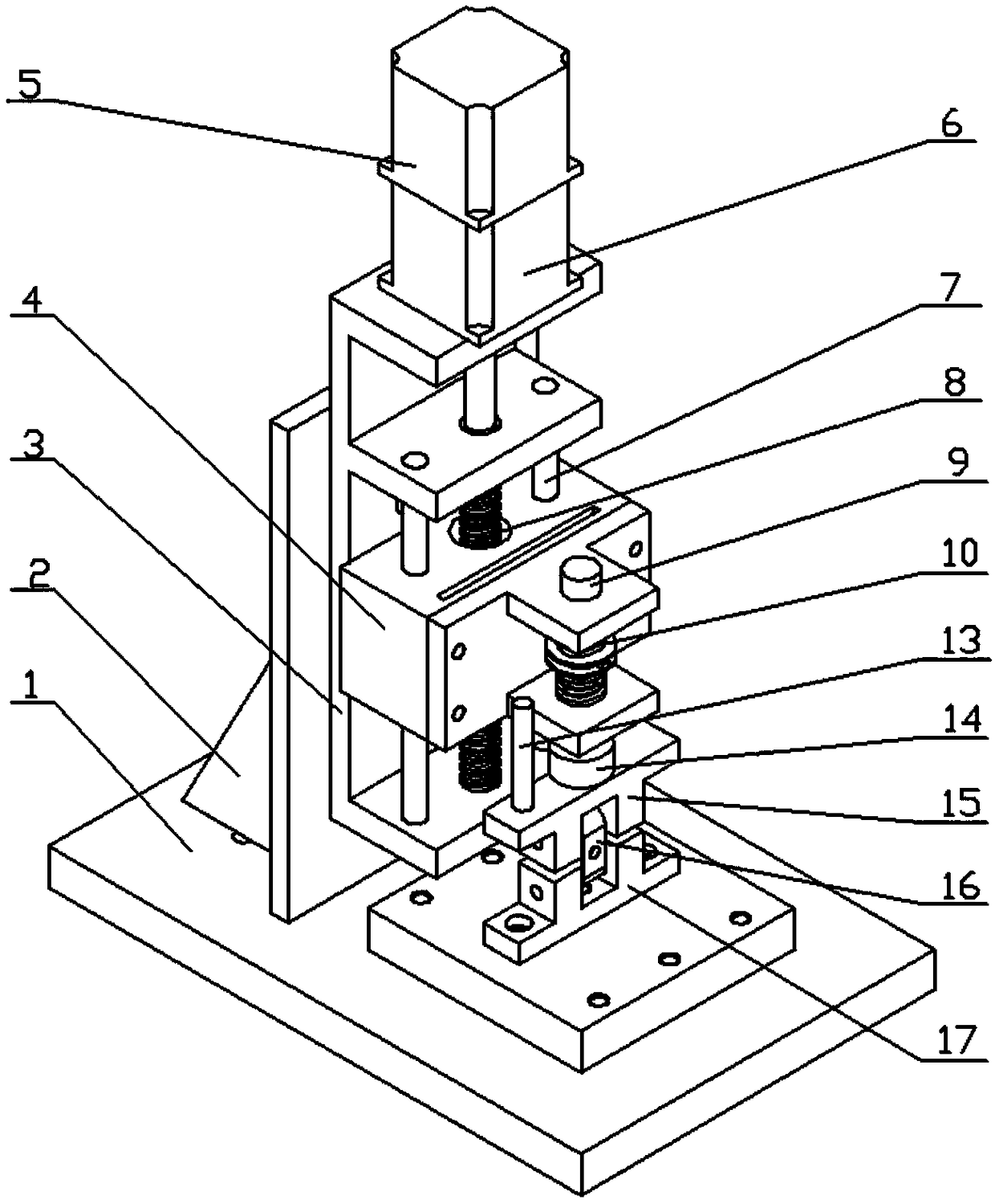
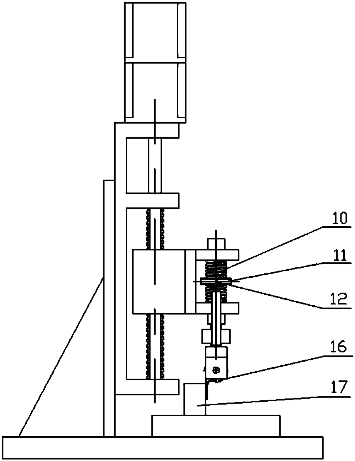
[0025] In the present invention, the orientation or positional relationship indicated by terms such as "upper", "lower", "left", "right", "front", "rear", "vertical", "horizontal" etc. are based on the drawings The orientation or positional relationship shown is just a relative term determined for the convenience of describing the structural relationship of the various components or elements of the present invention, and does not specifically refer to any component or element in the present invention, and should not be construed as a limitation of the present invention.

[0026] In the present invention, terms such as "connected" and "connected" should be understood in a broad sense, indicating that they can be fixedly connected, integrally connected or detachably connected; they can be directly connected or indirectly connected through an intermediary. For relevant researchers or technical personnel in the field, the specific meanings of the above terms in the present inventio...


PUM


Abstract

The invention discloses a device for automatically calibrating clamp rigidity and an application method thereof, and belongs to the field of machinery. The device for automatically calibrating clamp rigidity is used for fast and highly precise clamp rigidity calibration. In the process of calibrating the clamp rigidity, firstly an equilibrium position is adjusted, and a force sensor and a displacement sensor return to a home position; an industrial control computer sends out a command to control a stepping motor to drive a retarder to rotate, and to drive the entire screw nut slide table to move along a straight line through a screw nut pair; the displacement of the screw nut slide table is stably transmitted to a loading head through the action of a spring, and then the clamp is deformed;a collecting device synchronously collects signals from the force sensor and the displacement sensor and outputs the signals to the industrial control computer; the industrial control computer controls the stepping motor to stop rotating after the signal from the force sensor reaches a set value; and the stepping motor reverses again to a zero point when the stepping motor is reversed to a set reversed value. The device for automatically calibrating clamp rigidity and an application method thereof can obtain a force-displacement curve of the entire process through one-time clamping only, andobtain the rigidity of the clamp under a tension and compression state. The rigidity test process is smooth and continuous, and the rigidity measurement is accurate.

Description

technical field [0001] The invention belongs to the field of machinery, and relates to a device for testing the performance of pipeline clamps, in particular to an automatic calibration device for the stiffness of pipeline support clamps. Background technique [0002] Clamp is a connecting device for connecting grooved pipe fittings, valves and pipeline fittings. The fixed clamp with pad has a relatively simple structure, generally composed of a metal bracket and a pad, and is mainly used for the installation and fixing of conduits, wires and cables. The material of the gasket can be made of a variety of materials according to the requirements of use, mainly rubber with different properties, as well as plastics, glass fibers, and even metals. They play the role of fixing and damping vibration. At the same time, in order to meet different requirements of use, the pads have different structures. The pipe clamp plays an important part in enhancing the rigidity of the pipeline...

Claims


Application Information

Patent Timeline
IPC IPC(8): G01N3/08
CPCG01N3/08G01N2203/0017G01N2203/0019G01N2203/005
Inventor 韩清凯陶杨翟敬宇黎继武
Owner DALIAN UNIV OF TECH
Why Eureka
Try Eureka