An upper lamp box of a macroscopic inspection machine

A macro inspection and light box technology, applied in optics, instruments, photography, etc., can solve the problems of waiting time, lighting time, long lighting and extinguishing interval, low macro detection efficiency, etc., and achieve real-time use, real-time switching, The effect of improving efficiency

Pending Publication Date: 2018-12-28
SUZHOU JINGLAI OPTO CO LTD
0 Cites 2 Cited by

AI-Extracted Technical Summary

Problems solved by technology

Because the sodium light tube has the characteristics of a light-on time and a long time between light-on and extinguish, the existing upper light box ...

Method used

The present invention connects a sunshade 2062 by rotating on the light box 2061 of the sodium lamp 2068, the light of the sodium lamp 2068 can be cut off by rotating the sunshade 2062, so that when the metal lamp 203 is used, the sodium lamp 2068 need not be extinguished, and the sodium lamp 2068 isolated The light of the metal lamp 203 does not affect the light of the metal lamp 203, and the real-time switching between the metal lamp 203 and the sodium lamp 2068 i...

Abstract

The invention relates to the technical field of a lamp box structure, and discloses an upper lamp box of a macroscopic inspection machine, the box comprising a lamp box base and a lamp box main body,wherein, the lamp box main body comprises: a moving frame slidably connected with the lamp box base; a metal lamp assembly which includes a metal lamp fixing seat fixed on a moving frame, a metal lampmounted on the metal lamp fixing seat, and an optical glass disposed on the moving frame and positioned at a light focus of the metal lamp; a sodium lamp group arranged on the moving frame and offsetfrom the metal lamp, the sodium lamp group comprising at least two sodium lamp boxes, each sodium lamp box comprising an open type lamp box, a light shield assembly rotatably arranged on the lamp boxand capable of closing or opening an open opening of the lamp box, and a sodium lamp arranged in the lamp box; a drive mechanism provided on the moving frame to drive each of the shield assemblies torotate. The upper lamp box of the macroscopic inspection machine of the invention can switch the lamps of the sodium lamps and the metal lamp in real time.

Application Domain

Photography

Technology Topic

Moving frameEngineering +5

Image

  • An upper lamp box of a macroscopic inspection machine
  • An upper lamp box of a macroscopic inspection machine
  • An upper lamp box of a macroscopic inspection machine

Examples

  • Experimental program(1)

Example Embodiment

[0029] The technical solutions of the present invention will be further described below in conjunction with the drawings and specific implementations.
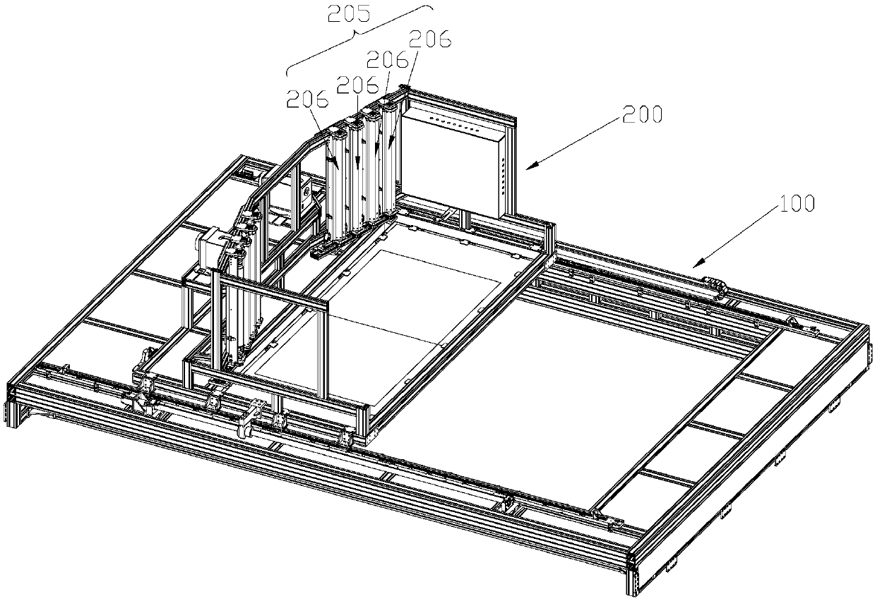
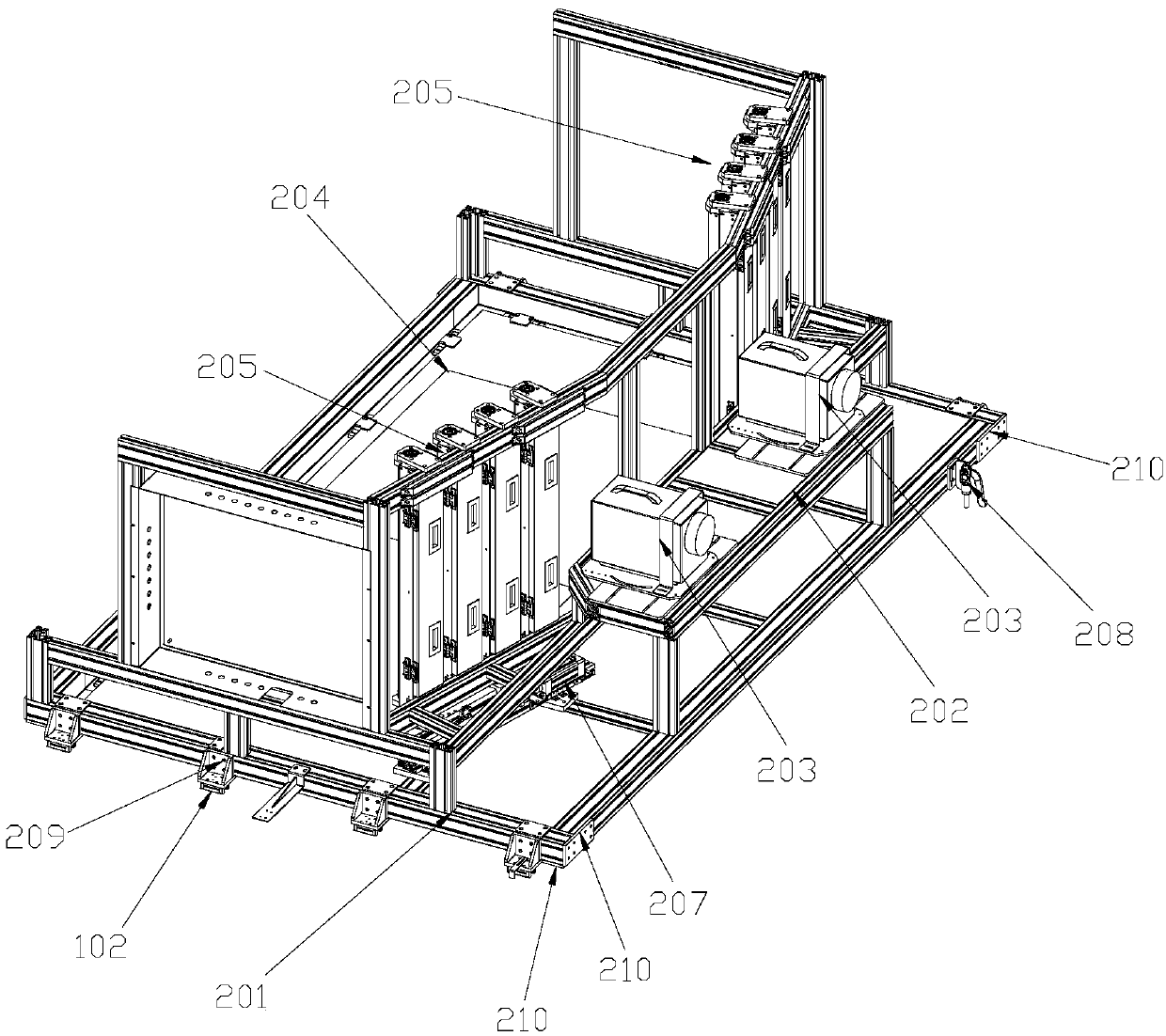
[0030] Such as figure 1 As shown, the upper light box of the macro inspection machine of the present invention includes a light box base 100 and a light box body 200.
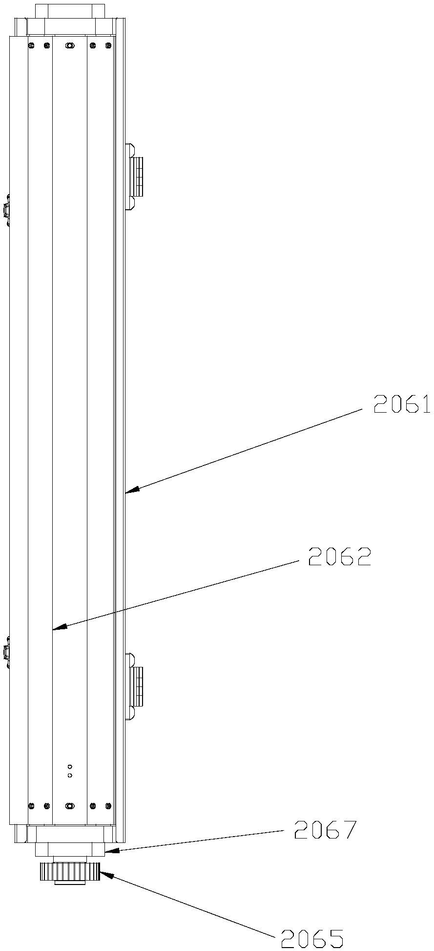
[0031] Such as Figure 1 to Figure 4 As shown, the light box main body 200 includes a moving frame 201, a metal lamp assembly, a sodium lamp group 205, and a driving mechanism 207. Among them, the mobile frame 201 is slidably connected to the light box base 100; the metal lamp assembly includes a metal lamp fixing base 202 fixed on the moving frame 201, a metal lamp 203 installed on the metal lamp fixing base 202, and a metal lamp 203 arranged on the moving frame 201 and located The optical glass 204 where the light of the metal lamp 203 is focused is used to converge or diffuse the tube of the metal lamp 203; the sodium lamp group 205 is arranged on the moving frame 201 and is staggered with the metal lamp 203, the sodium lamp group 205 includes At least two sodium lamp boxes 206, the sodium lamp box 206 includes an open light box 2061, a hood assembly that is rotatably arranged on the light box 2061 and capable of closing or opening the light box 2061, and a sodium lamp 2068 arranged in the light box 2061; a driving mechanism 207 It is arranged on the moving frame 201 to drive the rotation of each light shield assembly.
[0032] In order to meet the illumination requirements of the upper light box, the present invention is provided with two metal lamps 203 and two sets of sodium lamps 205 on the movable frame 201.
[0033] Specifically, the shade assembly can cover or expose the sodium lamp 2068, including a shade 2062 that can cover the opening of the light box 2061, a connecting plate 2063 connected to the end of the shade 2062, a drive shaft 2064 connected to the connecting plate 2063, and The transmission shaft 2064 is coaxially connected to the gear 2065, the maximum width of the connecting plate 2063 is smaller than the inner width of the light box 2061, and the transmission shaft 2064 is rotatably connected with the bearing 2067 on the end of the light box 2061.
[0034] The present invention connects a hood 2062 to the light box 2061 of the sodium lamp 2068 by rotating the hood 2062 to isolate the light of the sodium lamp 2068, so that when the metal lamp 203 is used, the sodium lamp 2068 does not need to be extinguished. The light of the metal lamp 203 has no effect, and the real-time switching of the metal lamp 203 and the sodium lamp 2068 is achieved, which improves the efficiency of macro detection; in addition, the sodium lamp 2068 does not need to be extinguished, ensuring that the sodium lamp 2068 can be used in real time.
[0035] In order to open or close the light shields 2062 on the sodium lamp boxes 206 of the sodium lamp group 205 at the same time, such as Figure 5 As shown, the driving mechanism 207 of the present invention includes a support plate 2071, a rack 2072 slidably connected to the support plate 2071, an air cylinder 2073 that drives the rack 2072 to slide along the support plate 2071, and the rack 2072 meshes with each gear 2065.
[0036] Since the movable frame 201 is slidably connected with the light box base 100, in order to prevent the movable frame 201 from sliding relative to the light box base 100 when repairing the upper light box of the present invention, the upper light box of the present invention also includes a lock that restricts the moving frame 201 from sliding relative to the light box base 100. Solid bodies, such as figure 2 with Image 6 As shown, the locking mechanism includes a toggle clamp 208 provided on the moving frame 201, and a recess 103 provided on the light box base 100 and located in a locked position. The toggle clamp 208 can be inserted into the recess 103.
[0037] In addition, for the convenience of powering off the upper light box when repairing the upper light box, the present invention also has a micro switch 104 electrically connected to the electric control system of the upper light box in the recess 103, and the toggle clamp 208 is inserted into the recess 103 Then, the micro switch 104 can be touched. During maintenance, the elbow clamp 208 is lowered and inserted into the pit 103, and the micro switch 104 in the pit 103 is triggered to power off the upper light box, which ensures that the upper light box will not move during maintenance and will not be energized, ensuring personnel safety.
[0038] In order to prevent the overall weight of the upper light box from being too heavy, the light box main body 200 moves stably and firmly. The light box base 100 and the movable frame 201 in the present invention are made of profiles. The profile has the characteristics of good load capacity and light weight.
[0039] The sliding connection between the moving frame 201 and the light box base 100 is achieved by arranging two parallel sliding rails 101 on the light box base 100. The sliding rails 101 are slidably connected with multiple sliders 102, and the bottom of the moving frame 201 is connected with multiple sliding rails. The welding pieces 209 are respectively welded to each slider 102 one by one. The welding piece 209 is used to connect the sliding block 102, so that the light box main body 200 will not produce abnormal noise due to looseness when moving.
[0040] In order to further avoid abnormal noise during the movement of the light box main body 200, the present invention is connected with a corner connecting plate 210 on one of the sides of the top corner of the movable frame 201 and the bottom surface corresponding to the side. The corner connecting plate 210 is connected to the top corner of the movable frame 201 to prevent the top corner from loosening.
[0041] In summary, the upper light box of the macro inspection machine of the present invention can switch the light of the sodium lamp 2068 and the light of the metal lamp 203 in real time, which solves the structure of the currently used upper light box that has structural instability, abnormal motion noise, abnormal motion, and light coverage. Insufficient, difficult to repair and other issues.
[0042] The technical principle of the present invention has been described above in conjunction with specific embodiments. These descriptions are only for explaining the principle of the present invention, and cannot be construed as limiting the protection scope of the present invention in any way. Based on the explanation here, those skilled in the art can think of other specific implementation manners of the present invention without creative work, and these manners will fall within the protection scope of the present invention.

PUM

no PUM

Description & Claims & Application Information

We can also present the details of the Description, Claims and Application information to help users get a comprehensive understanding of the technical details of the patent, such as background art, summary of invention, brief description of drawings, description of embodiments, and other original content. On the other hand, users can also determine the specific scope of protection of the technology through the list of claims; as well as understand the changes in the life cycle of the technology with the presentation of the patent timeline. Login to view more.

Similar technology patents

Systems and methods for notifying multiple hosts from an industrial controller

ActiveUS8150959B1reusable block of code very difficultimprove efficiency
Owner:ROCKWELL AUTOMATION TECH

Hybrid OLED having improved efficiency

InactiveUS20080284317A1improve efficiency
Owner:GLOBAL OLED TECH

Classification and recommendation of technical efficacy words

  • Improve efficiency
Why Eureka
Try Eureka