A Method for Optimizing Chip Fragility Based on Response Surface Modeling

A response surface method and fragility technology, applied in simulators, instruments, control/regulation systems, etc., can solve problems such as poor chip fragility, affecting processing efficiency, safety issues, etc., to improve processing efficiency and processing Safety, reduced processing costs, and high precision

Active Publication Date: 2021-04-30
UNIV OF ELECTRONICS SCI & TECH OF CHINA
View PDF6 Cites 0 Cited by
  • Summary
  • Abstract
  • Description
  • Claims
  • Application Information

AI Technical Summary

Problems solved by technology

[0006] However, the cost of obtaining more brittle chips by improving the indexable grooving tool is too high and wastes a lot of resources. Moreover, it is more complicated to implement, which affects the processing efficiency. security issues during

Method used


Image

  • A Method for Optimizing Chip Fragility Based on Response Surface Modeling
  • A Method for Optimizing Chip Fragility Based on Response Surface Modeling
  • A Method for Optimizing Chip Fragility Based on Response Surface Modeling

Examples


Embodiment 1

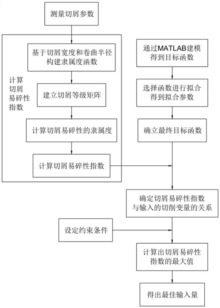
[0068] Such as figure 1 As shown, a method for optimizing chip friability based on response surface modeling includes the following steps:

[0069] a. Evaluate the chip friability and calculate the chip friability index C in ;

[0070] b. Modeling by response surface method RSM and optimizing chip friability.

[0071] In this embodiment, first of all, the fuzzy logic theory in fuzzy mathematics is applied to the establishment of a model for evaluating chip friability, and finally a model for evaluating chip friability is successfully established, and by defining chip friability Index C in Quantitatively expresses the fragility of chips, and provides output data for multivariate quadratic fitting using the response surface method. Then, using the method of implementing multivariate quadratic fitting in MATLAB, the function with the highest accuracy is selected through multiple simulations , finally obtained the multivariate quadratic objective function, and successfully est...

Embodiment 2

[0073] On the basis of embodiment 1, this embodiment includes the following steps before performing step a:

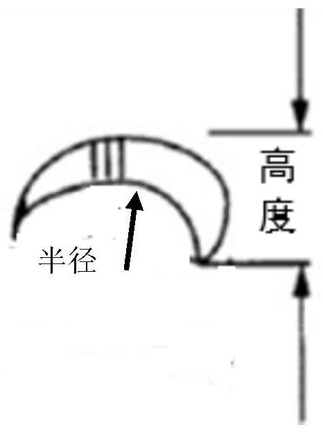
[0074] Measure chip parameters including chip width and chip curl radius. The chip width refers to the width value on a chip, not the length value. Since the range of the length value often exceeds the range that the instrument can measure, the measurement of the width value makes the evaluation of the calculated data more accurate; the chip curl radius is an item The index used to indicate the degree of curling of chips. Since the degree of curling is expressed by the radian of the curling part, it will make it difficult to define the specific curling part. Therefore, measuring the radius of the curling part to illustrate the degree of curling of chips can make the measurement data more accurate and facilitate the calculation of chips. Fragility Index.

Embodiment 3

[0076] In this embodiment, on the basis of embodiment 2, said step a includes the following steps:

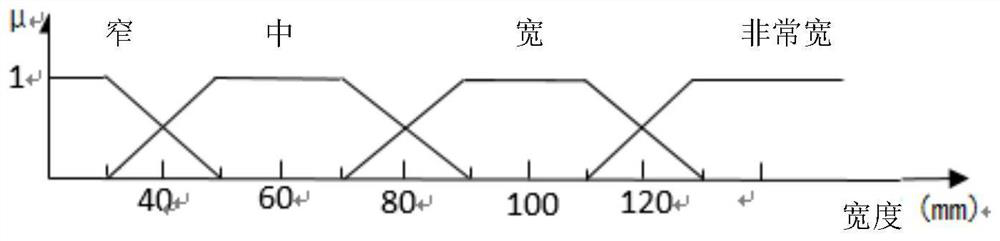
[0077] a101. Construct width membership function and curl radius membership function respectively based on chip width and curl radius:

[0078] Chip=S N (df 1 , df 2 )

[0079] where N represents the chip group whose dimensions are width and curl radius, df 1 and df 2 The size characteristics of chips can be blurred;

[0080] DF 1 =[μF 1i (df 1 ) / F1i (df 1 )]

[0081] DF 2 =[μF 2j (df 2 ) / F 2j (df 2 )]

[0082] Among them, F represents the grade level of the chip shape, DF 1 is the first dimension feature, DF 2 is the second dimension feature, μ is df 1 or df 2 membership degree value;

[0083] a102, establish chip shape matrix M:

[0084]

[0085] m N ={(A k ) ij}, i=1...m, j=1...n

[0086] Among them, i is the grade level of the chip shape of the first dimension feature, j is the grade level of the chip shape of the second dimension feature, A k ...


PUM


Abstract

The invention discloses a method for optimizing chip friability based on response surface modeling. First, the chip friability is evaluated, and the chip friability index C is calculated. in ; then modeled by response surface method RSM, and chip friability is optimized. The matching model between cutting parameters and chip friability was successfully established, and the optimal solution consistent with the experimental results was obtained, chip friability was optimized, and the calculation was accurate, which improved processing efficiency and processing safety and reduced processing time. cost, so that the quality of the obtained product is higher.

Description

technical field [0001] The invention relates to the technical field of numerical control machining, in particular to a method for optimizing chip friability based on response surface modeling. Background technique [0002] The chip formation process is essentially an extrusion process. During the extrusion process, the chipped metal mainly undergoes shear-slip deformation to form chips. When cutting plastic materials, when the workpiece is squeezed by the tool, as the tool continues to cut, the stress and strain inside the material gradually increase. When the generated stress reaches the yield point of the material, slippage or plastic deformation begins. [0003] Although chips seem to be just waste generated in CNC machining, various steel parts processed on lathes have good toughness, and chips generated during turning are full of plastic curls and sharp edges. When cutting steel parts at high speed, red hot and long chips will be formed, which are very easy to hurt p...

Claims


Application Information

Patent Timeline
Patent Type & Authority Patents(China)
IPC IPC(8): G05B17/02
CPCG05B17/02
Inventor 张培培韩泽祖
Owner UNIV OF ELECTRONICS SCI & TECH OF CHINA
Why Eureka
Try Eureka